Current Input
Input terminals A1 and A2 can accept a current input signal. Refer to Table 1.6 to set terminals A1 and A2 for current input.
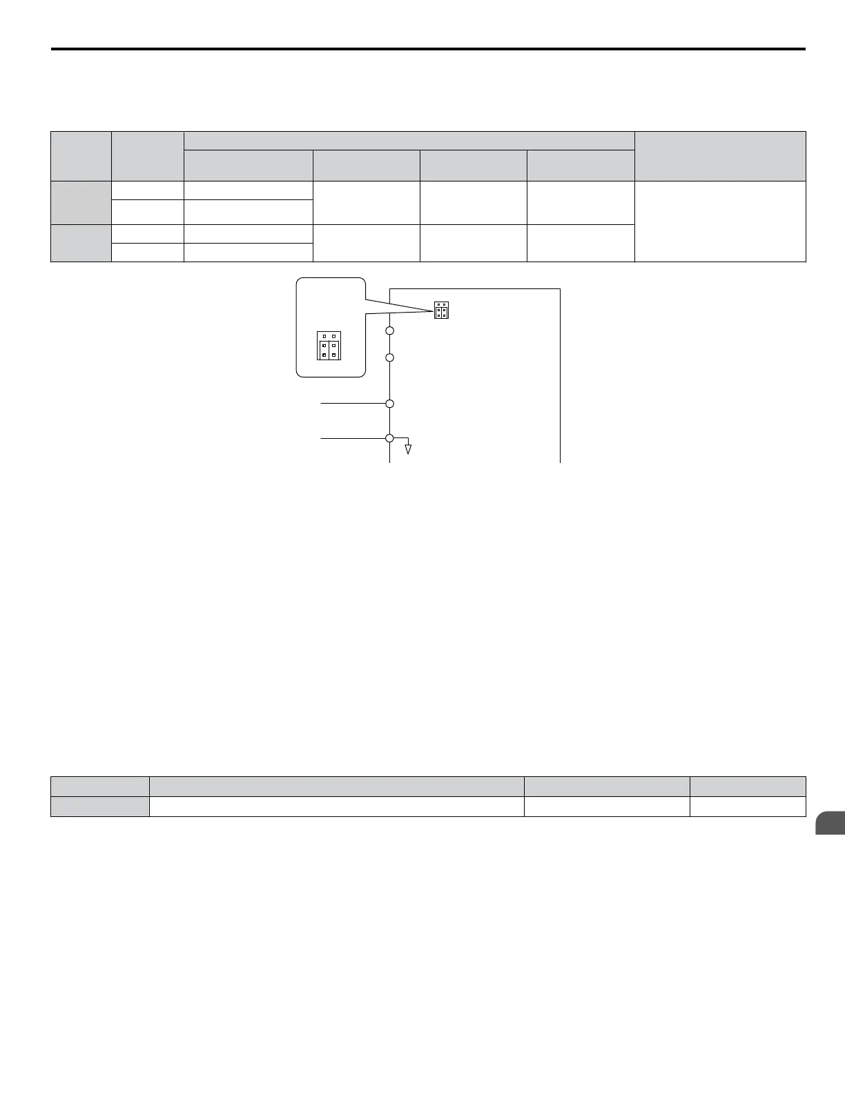
Table 1.6 Analog Input Settings for Frequency Reference Using a Current Signal
Terminal
Signal
Level
Parameter Settings
Notes
Signal Level
Selection
Function
Selection
Gain Bias
A1
4 to 20 mA H3-01 = 2 H3-02 = 0
(Frequency
Reference Bias)
H3-03 H3-04
Make sure to set Jumper S1 on the
terminal board to “I” for current
input.
0 to 20 mA H3-01 = 3
A2
4 to 20 mA H3-09 = 2
H3-10 = 0
(Frequency Bias)
H3-11 H3-12
0 to 20 mA H3-09 = 3
Drive
A1 Analog Input 1
0 or 4 to 20 mA
AC Analog input common
+V
10.5 V, 20 mA power supply
A2 Analog Input 2
V
I
A1 A2
Jumper S1
Terminal A1/A2
Voltage/Current
Selection
V
I
A1 A2
Figure 1.2 Setting the Frequency Reference as a Current Signal to Terminal A2
Switching between Main/Auxiliary Frequency References
The frequency reference input can be switched between the analog terminals A1 and A2 using multi-speed inputs. Refer to
Multi-Step Speed Selection on page 56 for details on using this function.
Setting 2: Serial Communication (APOGEE FLN, BACnet, MEMOBUS/Modbus, Metasys N2)
This setting requires entering the frequency reference via the RS-422/RS-485 serial communications port (control terminals
R+, R-, S+, and S-). Refer to MEMOBUS/Modbus Configuration on page 302 for instructions.
Setting 3: Option Card
This setting requires entering the frequency reference via an option board plugged into connector CN5 on the drive control
board. Consult the option card manual for instructions on integrating the drive with the communication system.
Note: If the frequency reference source is set for Option PCB (b1-01 = 3), but an option board is not installed, an oPE05 Programming Error will
be displayed on the HOA keypad and the drive will not run.
n
b1-02: Run Command Selection for AUTO Mode
Determines the Run command selection for AUTO mode.
No. Parameter Name Setting Range Default
b1-02 Run Command Selection for AUTO Mode 1 to 3 1
Setting 1: Control Circuit Terminal
This setting requires entering the Run command via the digital input terminals using one of following sequences:
• 2-Wire sequence 1:
Two inputs (FWD/Stop-REV/Stop). Set A1-03 to 2220 to initialize the drive and preset terminals S1 and S2 to these
functions. This is the default setting of the drive. Refer to Setting 40, 41: Forward Run, Reverse Run Command for 2-
Wire Sequence on page 78.
• 2-Wire sequence 2:
Two inputs (Start/Stop-FWD/REV). Refer to Setting 42, 43: Run and Direction Command for 2-Wire Sequence 2 on
page 78.
• 3-Wire sequence:
1.2 b: Application
YASKAWA SIEP YAIZ1U 03B YASKAWA AC Drive – Z1000 Programming Manual
25
1
Parameter Details

 Loading...


