Setting
Terminal Status
<1>
Detection Conditions
<2>
Stopping Method
N.O. N.C.
Always
Detected
Detected
during Run
only
Ramp to Stop
(fault)
Coast to Stop
(fault)
Fast Stop
(fault)
Alarm Only
(continue
running)
24 O - O - - O - -
25 - O O - - O - -
26 O - - O - O - -
27 - O - O - O - -
28 O - O - - - O -
29 - O O - - - O -
2A O - - O - - O -
2B - O - O - - O -
2C O - O - - - - O
2D - O O - - - - O
2E O - - O - - - O
2F - O - O - - - O
<1> Determine the terminal status for each fault, i.e., whether the terminal is normally open or normally closed.
<2> Determine whether detection for each fault should be enabled only during run or always detected.
Setting 30: PI Integral Reset
Configuring one of the digital inputs for PI integral reset (H1-oo = 30) resets the value of the integral component in PI control
to 0 when the terminal is closed. Refer to PI Block Diagram on page 39 for more details.
Setting 31: PI Integral Hold
Configuring a digital input for Integral Hold (H1-oo = 31) locks the value of the integral component of the PI control as long
as the input is active. The PI controller resumes integral operation from the hold value as soon as the integral hold input is
released. Refer to PI Block Diagram on page 39 for more information on this function.
Setting 34: PI Soft Starter Cancel
A digital input configured as a PI soft starter cancel input (H1-oo = 34) enables or disables the PI soft starter and cancels
the PI accel/decel time (b5-17). Refer to PI Block Diagram on page 39.
Setting 35: PI Input Level Selection
Allows an input terminal to switch the sign of the PI input. Refer to PI Block Diagram on page 39 for details.
Setting 40, 41: Forward Run, Reverse Run Command for 2-Wire Sequence
Configures the drive for a 2-Wire sequence.
When an input terminal set to 40 closes, the drive operates in the forward direction. When an input set for 41 closes, the drive
operates in reverse. Closing both inputs simultaneously will result in an external fault.
Note: 1. This function cannot be used simultaneously with settings 42 and 43.
2. The same functions are assigned to terminals S1 and S2 when the drive is initialized for 2-Wire sequence.
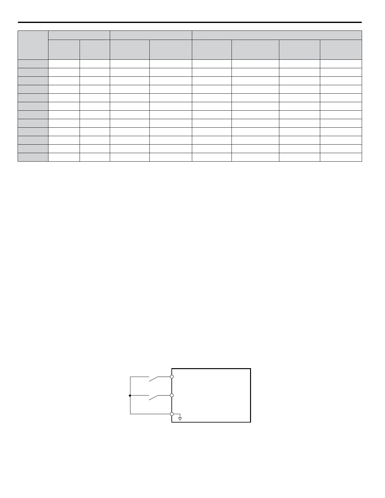
S1
S2
SN
Drive
Forward Run
Reverse Run
Standard Digital
Input Common
Figure 1.37 Example Wiring Diagram for 2-Wire Sequence
Setting 42, 43: Run and Direction Command for 2-Wire Sequence 2
Sets the drive for 2-Wire sequence 2.
1.7 H: Terminal Functions
78
YASKAWA SIEP YAIZ1U 03B YASKAWA AC Drive – Z1000 Programming Manual

 Loading...


