The following inputs can be used on MXLOGGER or MX100/DARWIN API sold
separately. These inputs cannot be used on the MX100 Standard Software.
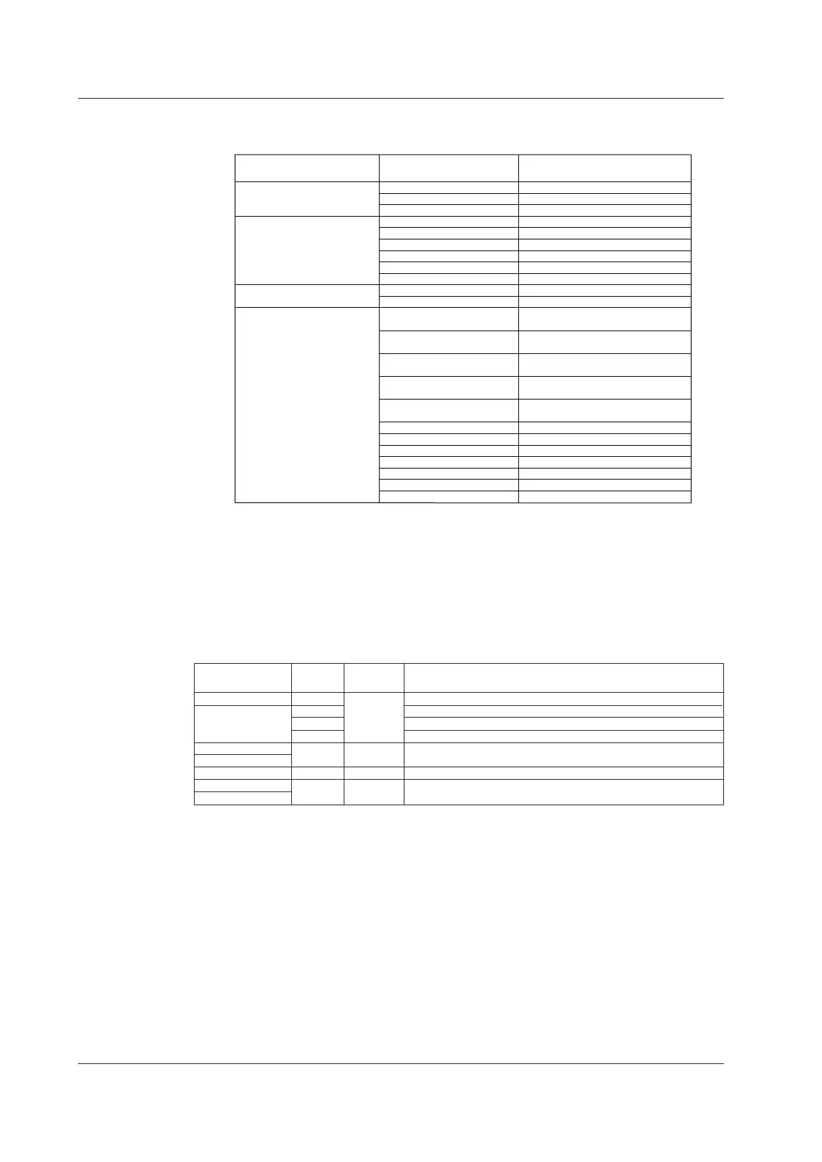
Input
DC voltage
60mV (high resolution)
1V
6V (high resolution)
PLATINEL
PR40-20
NiNiMo
WRe3-25
W/WRe26
Type-N(AWG14)
Pt100 (high noise resistance)
JPt100 (high noise resistance)
Cu10 at 20°C
alpha = 0.00392
Cu10 at 20°C
alpha = 0.00393
Cu25 at 0°C
alpha = 0.00425
Cu53 at 0°C
alpha = 0.00426035
Cu100 at 0°C
alpha = 0.00425
Pt25(JPt100*1/4)
Cu10 GE (high resolution)
Cu10 L&N (high resolution)
Cu10 WEED (high resolution)
Cu10 BAILEY (high resolution)
Pt100 (noise resistance)
JPt100 (noise resistance)
0.000 to 60.000mV
-1.0000 to 1.0000V
0.0000 to 6.0000V
0.0 to 1400.0°C
0.0 to 1900.0°C
0.0 to 1310.0°C
0.0 to 2400.0°C
0.0 to 2400.0°C
0.0 to 1300.0°C
-200.0 to 600.0°C
-200.0 to 550.0°C
-200.0 to 300.0°C
-200.0 to 300.0°C
-200.0 to 300.0°C
-50.0 to 150.0°C
-50.0 to 150.0°C
-200.0 to 550.0°C
-200.0 to 300.0°C
-200.0 to 300.0°C
-200.0 to 300.0°C
-200.0 to 300.0°C
-200.0 to 250.0°C
-200.0 to 250.0°C
Rated Measurement Range
RTD
(Measurement current:1 mA)
Thermocouple
RTD
(Measurement current: 2 mA)
Measurement Range Type
Measurement Interval, Integration Time, and Filter
The table below shows the available measurement intervals. The module is equipped
with an integrating A/D converter. The selectable integration time varies depending on
the measurement interval as shown in the table below. For details about the relationship
between noise and integration time, see section 2.7, “Measures against Noise on the
MX100 Data Acquisition Unit.”In addition, the type of noise rejection filter switches as
shown in the table below.
Measurement
Interval
10 ms
1.67 ms
16.67 ms
20 ms
Auto
Integration
Time
Filter
Rejected Noise and Notes
50 ms
Rectangular
100 ms
200 ms
500 ms
1 s
2, 5,10, 20, 30, 60 s
36.67 ms
100 ms
Trapezoidal
Rectangular
Cos
600 Hz and its integer multiples, temperature measurement not possible
60 Hz and its integer multiples
50 Hz and its integer multiples
Automatically detects the power supply frequency and set 16.67 or 20 ms
50 Hz or 60 Hz and their integer multiples
10 Hz and its integer multiples
Fc = 5-Hz low-pass filter
200 ms
Measurement Synchronization
Each input channel has its own A/D converter. Therefore, measurements on each
channel are synchronized.
Common Mode Voltage
The common mode voltage between channels in a single module is 250 VACrms when
the signal is applied continuously.
The common mode voltage between modules and between a module and earth is 600
VACrms when the signal is applied continuously.
1.3 Functions of the 4-CH, High-Speed Universal Input Module