2-23
IM MX100-01E
Installation and Wiring
Measurement
Interval
Integration
Time
Rejected Frequencies and Notes
4-CH, Medium-Speed Strain Input Module
100 ms
200ms
500 ms
1 s
2 s
5, 10, 20, 30,60 s
1.67 ms
16.67 ms
20 ms
Auto
36.67 ms
100 ms
200 ms
600 Hz and its integer multiples*
60 Hz and its integer multiples
50 Hz and its integer multiples
Automatically detects the power supply frequency and set 16.67 or 20 ms
50 Hz and 60 Hz and their integer multiples
10 Hz and its integer multiples
Low-pass filter with Fc = 5 Hz
* When the measurement interval is 100 ms, measured values may fluctuate since power supply frequency
noise is not rejected.
In such cases, set the measurement interval to 200 ms or more.
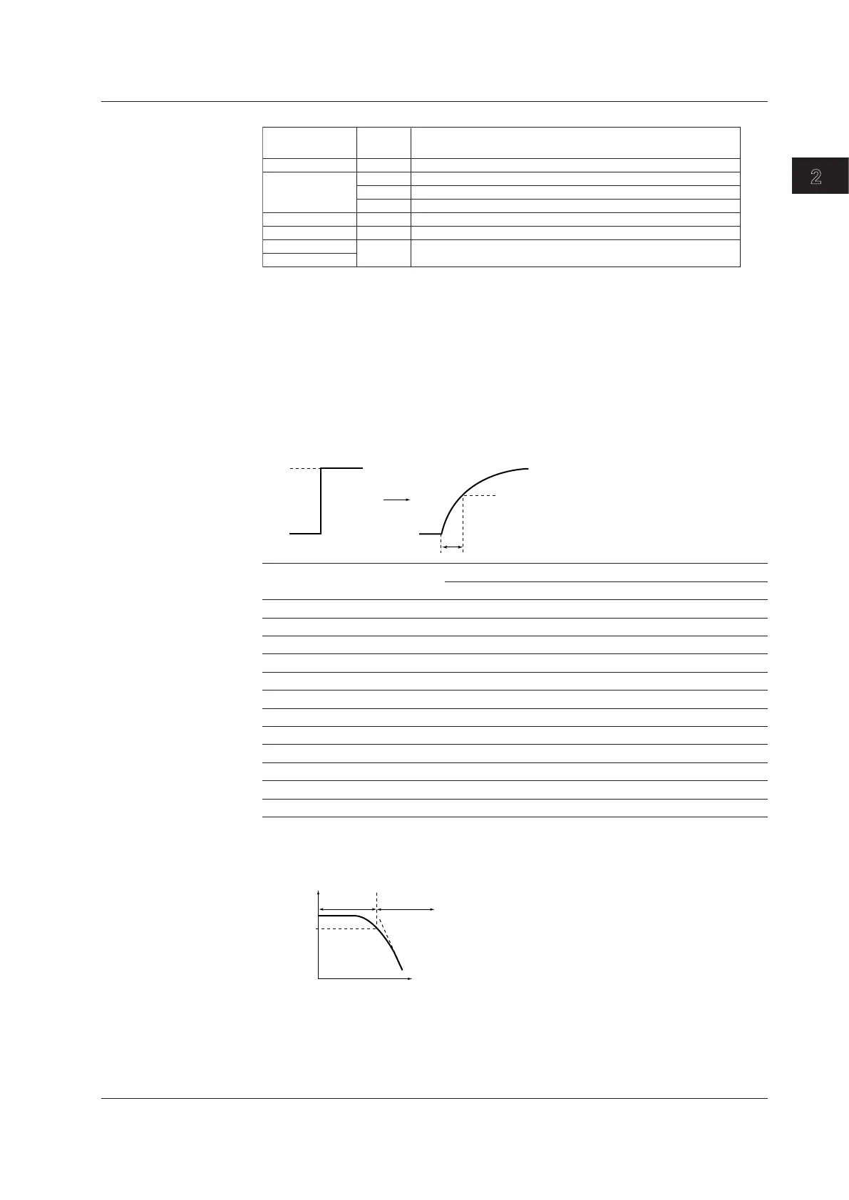
First-Order Lag Filter
For noise sources other than power supply noise, the MX100 Data Acquisition Unit is
equipped with a first-order lag filter having output characteristics indicated in the figure
below against step input. The time constant of the first-order lag filter can be selected on
the PC software (MX100 Standard Software, MXLOGGER (sold separately), or the API
for the MX100/DARWIN (sold separately)).
Step input
63.2% of the output value
Time constant
0%
100%
Output characteristics
Measurement Interval (s) Selectable Time Constants (s)
n=5 n=10 n=20 n=25 n=40 n=50 n=100
0.01 0.05 0.1 0.2 0.25 0.4 0.5 1
0.05 0.25 0.5 1 1.25 2 2.5 5
0.1 0.5 1 2 2.5 4 5 10
0.2 1 2 4 5 8 10 20
0.5 2.5 5 10 12.5 20 25 50
1 5 10 20 25 40 50 100
2 10 20 40 50 80 100 200
5 25 50 100 125 200 250 500
10 50 100 200 250 400 500 1000
20 100 200 400 500 800 1000 2000
30 150 300 600 750 1200 1500 3000
60 300 600 1200 1500 2400 3000 6000
If the first-order lag filter is applied to the input signal, low-pass filter frequency
characteristics shown in the figure below are attained.
Cutoff band
0dB
–3dB
Pass band
Frequency
Attenuation
Cutoff frequency
If the time constant of the first-order lag filter is set long, the cutoff frequency is lowered,
and frequency bandwidth that can be rejected is widened. Set an appropriate time
constant according to the frequency of the noise you wish to reject.
2.7 Measures against Noise on the MX100 Data Acquisition Unit