3.3 Calibration
It is recommended that the MX100 be calibrated once a year to assure its measurement
accuracy. A calibration instrument with an appropriate accuracy and resolution is required
for calibrating the MX100.
Range Calibration of DC Voltage, RTD, Resistance, Strain, and Analog Output
Required Instruments
• DC voltage/current standard
Must meet the following specifications (M/9100 by FLUKE or equivalent)
Output range: 20 mV to 100 V
Accuracyintheoutputrange:±(0.01%+1µV)orless
• Resistance standard
Must meet the following specifications (ADR3204 by Alpha Electronics or equivalent)
Resistancemeasuringrange:0.1to3000Ω
Accuracyintheresistancerange:±(0.01%+2mΩ)orless
Resolution:0.001Ω
• Bridge head (Yokogawa Electric 319300)
• Digital multimeter
Must meet the following specifications (7562 by Yokogawa or equivalent)
Accuracy:±0.01%orless
Calibration Procedure
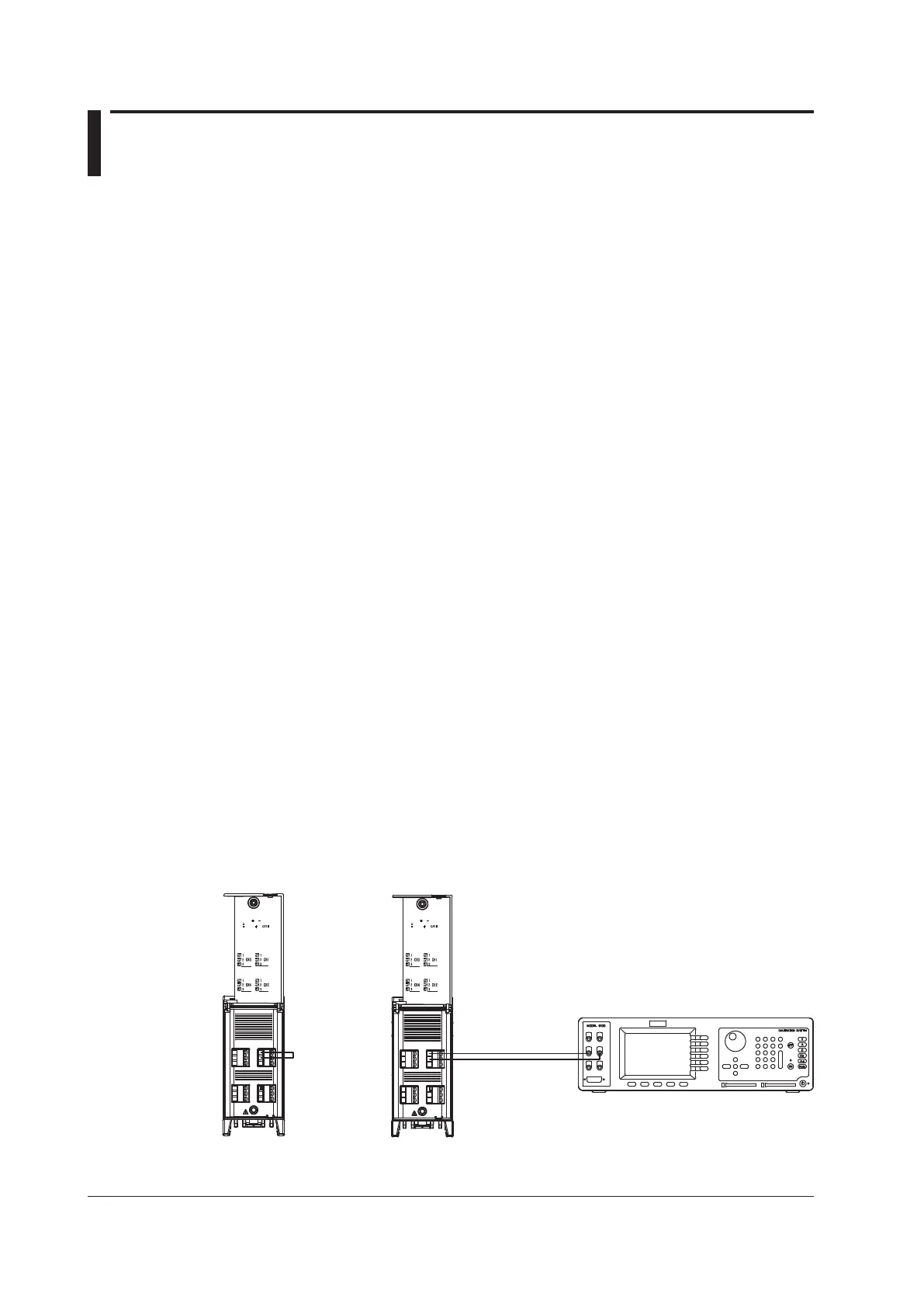
1. Wire the module being calibrated and the calibration instrument as shown in the figure
below, and adequately warm up the MX100 Data Acquisition Unit (the warm-up time of
the MX100 Data Acquisition Unit is at least 30 minutes).
2. Check that the operating environment such as ambient temperature and humidity is
within the standard operating conditions (see sections 4.4 through 4.7).
3. Connect the PC and the MX100 Data Acquisition Unit so that communication is
possible. Start the Calibrator of the MX Standard Software, and then start the
calibration. For the operating procedure of the Calibrator, see the MX Standard
Software User’s Manual (IM MX180-01E).
Wiring Diagram
• When calibrating the DC voltage range of the 4-CH, High-Speed Universal Input
module
Hi
Lo
100Vpk MAX TO
250V MAX CH TO CH
600V MAX TO
100Vpk MAX TO
250V MAX CH TO CH
600V MAX TO
When calibrating 0 V
When calibrating a range other than 0 V
DC voltage/current standard
Input terminal
+
–
Input terminal
+
–
Short
* Carry out calibration for each input terminal.