• Keep the ambient temperature consistent. Large temperature fluctuations occur in
such cases as when a fan nearby is turned ON/OFF.
Connecting the input wires in parallel with other instruments may mutually affect the
measured values.
If you need to make a parallel connection:
• Turn OFF burnout.
• Ground each instrument at a single common point.
• Do not turn ON/OFF the instrument while measurement is in progress. It may cause
adverse affects on the other instrument.
Note that RTDs and resistors cannot be connected in parallel.
Wiring Procedure
1. Turn OFF the power to the MX100.
2. Loosen the terminal cover attachment screw and lift up the terminal cover.
3. Connect the signal wires to the terminals.
4. Return the terminal cover to the original position and secure it with the screw.
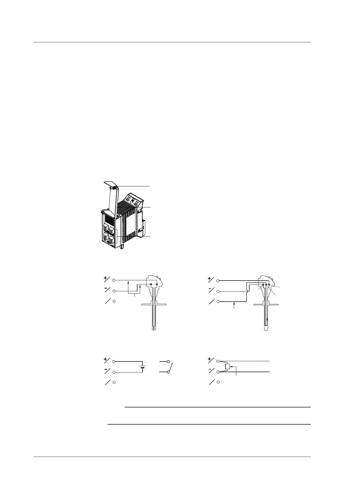
Input terminal (clamp terminal)
Terminal cover
4-CH, High-Speed Universal Input Module
Attachment screw for terminal cover
Wiring the Universal Input Modules
• Thermocouple input
• DC voltage input/DI input (contact)
• RTD input
• DC current input
DC current input
Shunt resistor
Example: For 4 to 20 mA input,
shunt resistance values should
be 250 Ω±0.1%.
–
+
Lead wire resistance per wire of
10 Ω or less*. Make the
resistance of the three wires equal.
A
b
B
Compensation
lead
b
A
B
b
A
B
b
A
B
* In the case of Pt100Ω. 5 Ω max
for Pt50Ω. 1 Ω max. for Cu10 Ω.
+
–
DC voltage
input
b
A
B
Contact
or
Note
On the 10-CH, Medium-Speed Universal Input module, RTD input terminals A and B are
isolated on each channel. Terminal b is shorted internally across all channels.
Teraminal type: Clamp
Applicable wire size: H04: 0.2 to 2.5mm
2
(AWG24 to 12)
M10: 0.14 to 1.5mm
2
(AWG26 to 16)
2.4 Connecting the Signal Wires