2.7 Measures against Noise on the MX100 Data
Acquisition Unit
Technical Information described below on measures against noise is available
as reference material. For information on obtaining a copy, contact your nearest
YOKOGAWA dealer.
• Noise Interference on Recorder (TI 4D5B1-80E)
Describes the fundamentals concerning noise and its countermeasures in two parts:
basic edition and application edition.
• MX100 Performance Specifications (TI 04M08B01-00E)
Describes in detail the functions related to noise rejection specific to the MX100 Data
Acquisition Unit.
This section briefly describes the integrating A/D converter and the first-order lag filter
that the MX100 Data Acquisition Unit employs as measures against noise.
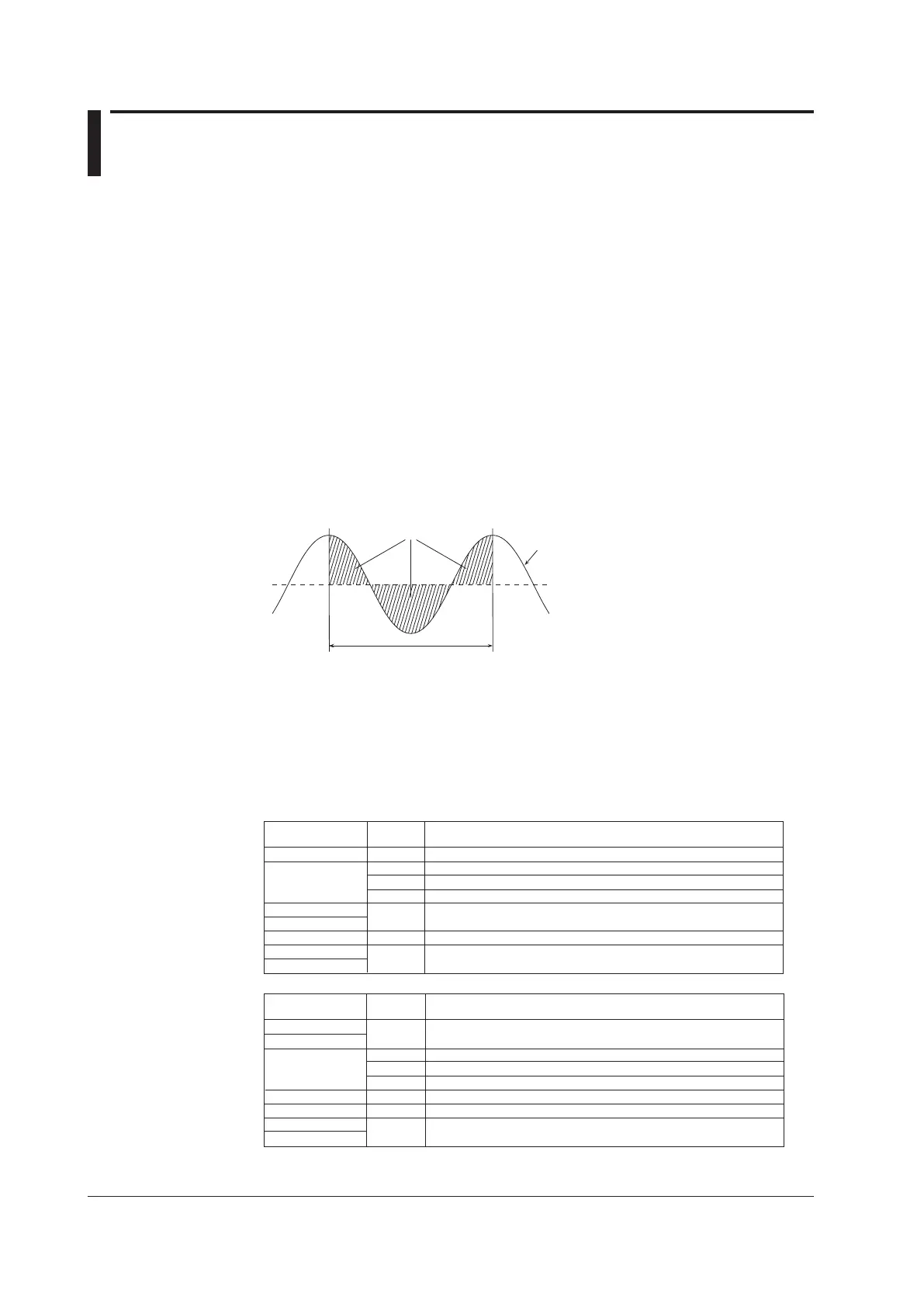
Integrating A/D Converter
MX100 input modules employ an integrating A/D converter for converting the measured
analog signals into digital signals. The integrating A/D converter integrates the measured
values at the specified time width. If the specified time spacing matches the period of the
signal you wish to reject, the signal is rejected.
Cancelled out
Integration time
DC voltage (average value)
Input voltage
(instantaneous value)
For example, if the integration time is 20 ms, signals having frequencies of 50 Hz and
integer multiples of 50 Hz can be rejected. Likewise, if the integration time is 16.67 ms,
signals having frequencies of 60 Hz and integer multiples of 60 Hz can be rejected. If
the integration time is 100 ms, signals having 10 Hz and integer multiples of 10 Hz can
be rejected. The commercial power supply is one of the noise sources. By setting these
integration times, commercial power noise of 50 Hz or 60 Hz can be eliminated.
The table below shows the integration times assigned to the MX100.
Measurement
Interval
10 ms
1.67 ms
16.67 ms
20 ms
Auto
Integration
Time
Rejected Frequencies and Notes
50 ms
100 ms
200 ms
500 ms
1 s
2, 5,10, 20, 30, 60 s
36.67 ms
100 ms
200 ms
600 Hz and its integer multiples, temperature measurement not possible
60 Hz and its integer multiples
50 Hz and its integer multiples
Automatically detects the power supply frequency and set 16.67 or 20 ms
50 Hz and 60 Hz and their integer multiples
10 Hz and its integer multiples
Low-pass filter with Fc = 5 Hz
4-CH, High-Speed Universal Input Module
Measurement
Interval
100 ms
16.67 ms
20 ms
Auto
Integration
Time
Rejected Frequencies and Notes
500 ms
1 s
2 s
5 s
10, 20, 30, 60 s
36.67 ms
100 ms
200 ms
600 Hz and its integer multiples*
60 Hz and its integer multiples
50 Hz and its integer multiples
Automatically detects the power supply frequency and set 16.6 or 20 ms
50 Hz and 60 Hz and their integer multiples
10 Hz and its integer multiples
200 ms
1.67 ms
6-CH, Medium-Speed 4-wire RTD Resistance Input Module/10-CH, Middle-Speed Universal Input Module
Low-pass filter with Fc = 5 Hz
* Because the power supply frequency noise is not rejected, measured values may fluctuate particularly for temperature
measurements using thermocouples. If this happens, make the measurement interval longer, or use the 4-CH High-Speed
Universal Input Module.