Alarms
The main module compares the measured values against preset alarm values and
outputs alarm signals based on the result from the digital output module. The following
four types of alarms can be output.
• Upper limit alarm
Generates an alarm when the measured value exceeds the alarm value.
• Lower limit alarm
Generates an alarm when the measured value falls below the alarm value.
• Differential upper limit alarm (during difference computation)
Generates an alarm when the difference in the measured values of two channels
exceeds the alarm value.
• Differential low limit alarm (during difference computation)
Generates an alarm when the difference in the measured values of two channels falls
below the alarm value.
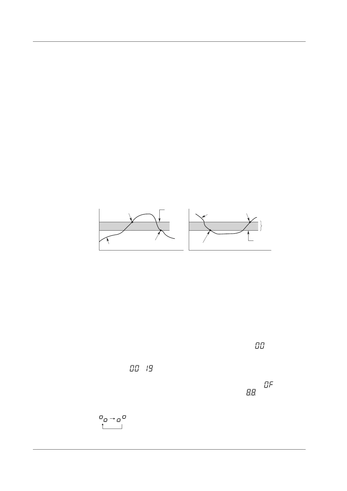
Alarm Value Hysteresis
You can set a width (hysteresis) to the values used to activate and release alarms. Alarm
hysteresis can prevent frequent activation and release of alarms when the measured
value is unstable around the alarm value.
Alarm
setting
Alarm release
Measured vale
Alarm activated
Upper limit alarm
Lower limit alarm
Measured value
Alarm release
Hysteresis
Alarm setting
Alarm activated
Alarm Output Timing
The output update interval is fixed at 100 ms. Therefore, when the measurement interval
is 10 ms or 50 ms, the alarm output data is accumulated over 100-ms intervals and
output at 100-ms intervals based on the accumulated data.
Contents Displayed on the 7-Segment LED
The two-digit 7-segment LED displays the unit number, operating status, operation
complete, and operation error of the MX100 Data Acquisition Unit.
Unit Number Display
Since a single MX100 Data Acquisition Unit can be connected to a PC on the MX100
Standard Software, the unit number is fixed to 00 and displayed as . When using
MXLOGGER (software sold separately) that allows up to twenty MX100 Data Acquisition
Units to be connected, the unit number can be set in the range from 00 to 19 and
displayed as to .
Display of the Self-Test Operation at Power On
When the power is turned ON the dip switch indicator lights (normally “ ”when the
/DS option is installed), the operation ready indicator lights (the display, and others),
then the self-test is carried out. While the self-test is in progress, the following symbols
are alternately displayed.
1.2 Main Module Functions
 Loading...
