Wiring the Digital Input Modules (-D05, -D24)
Note
On the digital input modules, the negative terminals and empty terminals of all channels are
shorted internally.
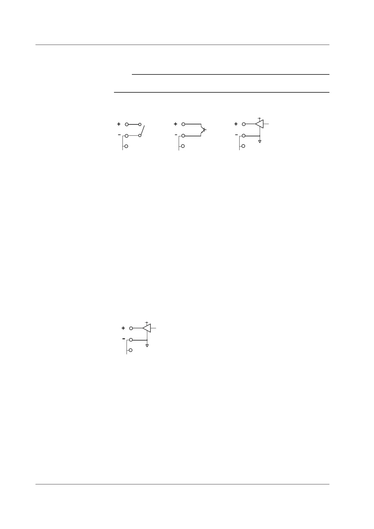
Wiring with the -D05 Option
• Transistor input
• Contact input
• 5V logic input
Main Input Specifications (-D05)
Input type: DI (non-voltage contact, open collector, and 5 V logic)
Inputformat: Pull-up at approximately 5 V/approximately 5 kΩ, common
electric potential between channels
Min. detection pulse width:
Twice the sampling interval or more
Input threshold level:
Non-voltagecontact,opencollector:ONat100Ωorlessand
OFFat100kΩorgreater
5-V logic: OFF at 1 V or less and ON at 3 V or greater
Contact/transistor rating:
Contact with a rating of 15 VDC or greater and 30 mA or
greater
Transistor with a rating of Vce > 15 Vdc and Ic > 30 mA
Terminal type: Clamp
Applicable wire size: 0.14 to 1.5 mm
2
(AWG26 to 16)
Wiring with the -D24 Option
Main Input Specifications (-D24)
Input type: DI (24 V logic)
Input format: Common potential between ch
Min. detection pulse width:
Twice the sampling interval or more
Input threshold level: 24 V logic: OFF at 6 V or less and ON at 16 V or greater
Terminal type: Clamp
Applicable wire size: 0.14 to 1.5 mm
2
(AWG26 to 16)
2.4 Connecting the Signal Wires