2.4 Connecting the Signal Wires
Terminal Arrangement Markings on the Terminal Cover
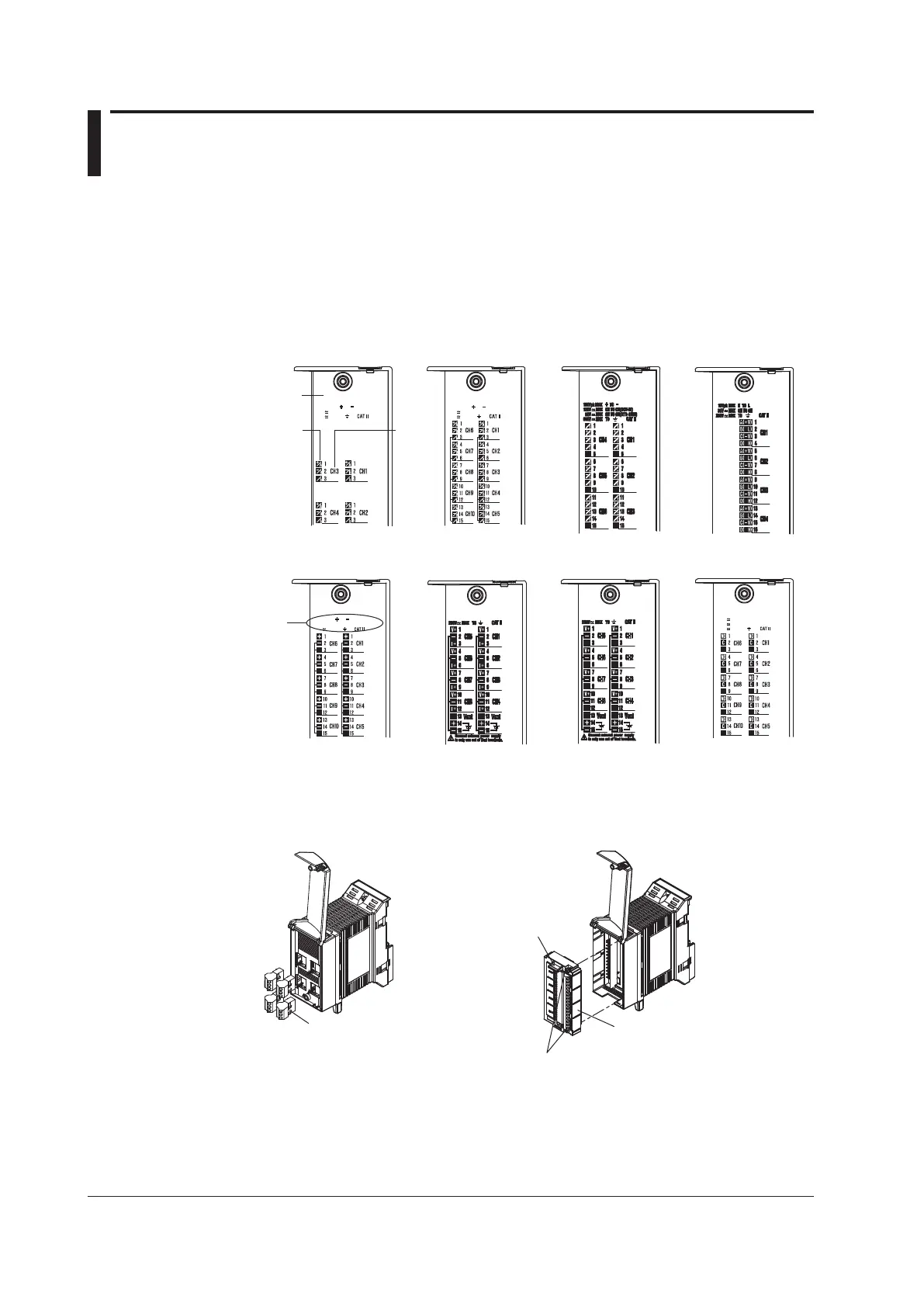
A character indicating the terminal function and a terminal symbol indicating the type of
signal to be input/output at each terminal are written on the back of the terminal cover of
each I/O module. For the wiring procedure corresponding to each terminal symbol, see
page 2-10. Note that the 4-CH, Medium-Speed Strain Input Module (-NDI) does not have
a terminal cover.
Terminal
cover
Channel
number
within
module
Terminal
symbol
-D05
100Vpk MAX TO
250V MAX CH TO CH
600V MAX TO
100Vpk MAX TO
120V MAX CH TO CH
600V MAX TO
250V MAX CH TO CH
250V MAX NO TO C
250V MAX TO
10Vpk MAX TO
250V MAX TO
4-CH, High-Speed
Universal Input Module
10-CH, Medium-Speed
Universal Input Module
6-CH, Medium-Speed
4-wire RTD Resistance
Input Module
4-CH, Medium-Speed
Strain Input Module
(-B12, -B35)
10-CH, High-Speed
Digital Input Module
(-D05, -D24)
8-CH, Medium-Speed
Analog Output Module
8-CH, Medium-Speed
PWM Output Module
10-CH, Medium-Speed
Digital Output Module
Attaching and Removing the Terminal Block
The I/O terminals can be removed as shown in the figure below.
4-CH, High-Speed Universal
Input Module
The terminal block can
be attached and
detached.
4-CH, Medium-Speed Strain
Input Module (-B12, -B35)
Pull-out
handle
The terminal plate can be
attached and detached.
Attachment screw
(Loosen before removing the terminal plate.)