2.3 Attaching the Modules
WARNING
To prevent electric shock and instrument breakdown, do not connect the power
supply to the main module when attaching modules.
Attachment Procedure
1. Check that the power supply is not connected to the main module.
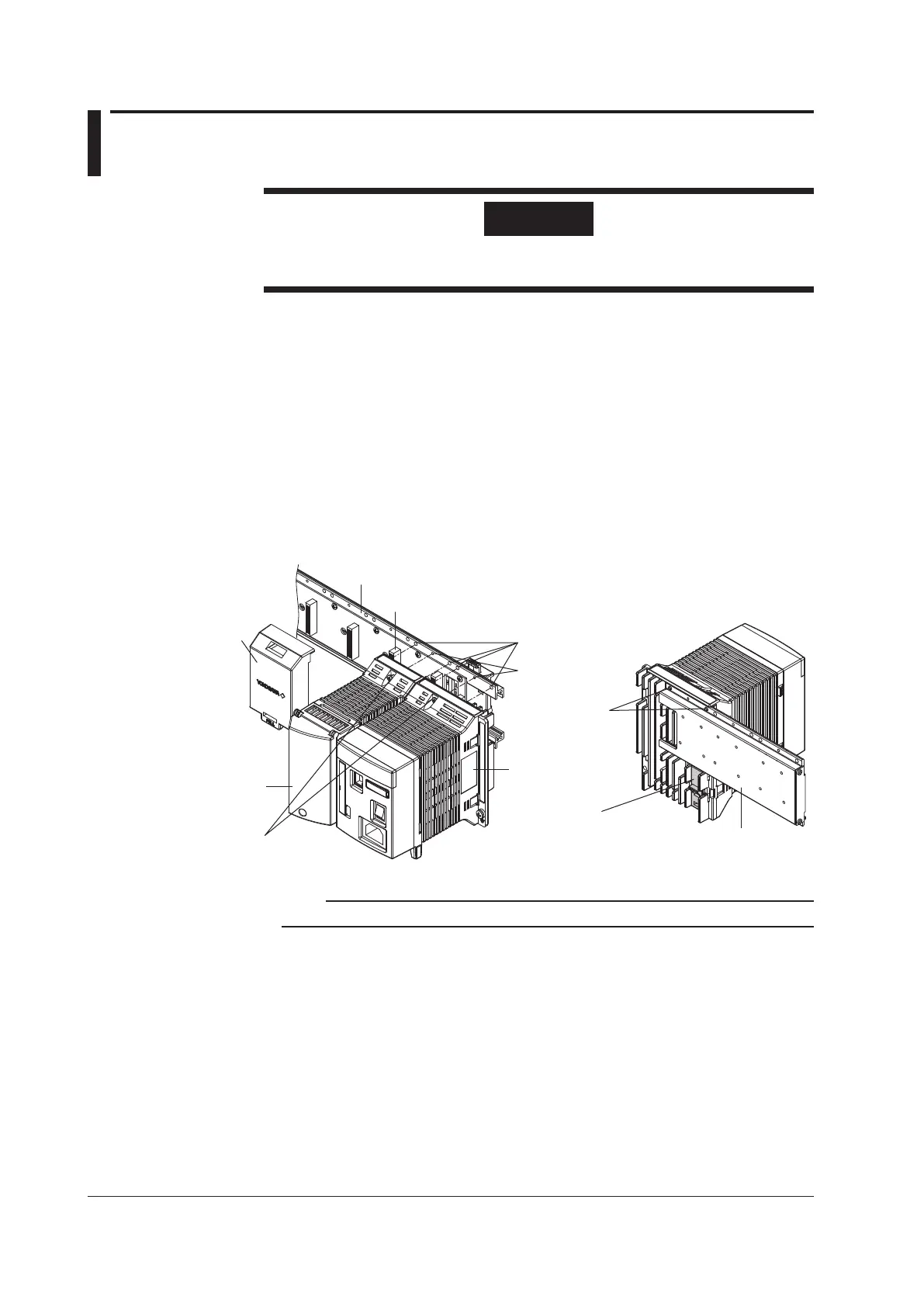
2. Align the connector on the rear panel of the module to the connector at the desired
position of the base plate and insert the connector.
When the connectors are correctly connected, the guide pin on the rear panel of the
module is inserted into the guide hole on the base plate. In addition, the module is
secured to the base plate with the latch lever locking in place at the bottom section of
the base plate.
3. Fasten the attachment screw (M3) at one location at the top of the module.
To remove the module, loosen the attachment screw, pull down on the latch lever on the
rear panel of the module, and pull the module straight from the base plate.
Module connector**
Base plate connector
cover*
(accessory sold
separately)
Screw holes
Guide holes
Main module
Input/Output module
Base plate
Base plate
Latch lever
(pull up to remove the
module from the base plate)
Guide pins
Module attachment screw
* Can be attached by
hooking the top section of
the cover to the top edge
of the base plate and
pressing down on the
lower section of the cover.
** When attaching the module, be sure that the
module connector is vertical to the base plate
so that the module connector pins are not bent.
Note
The main module can only be attached to the right end of the base plate.