2-15
IM MX100-01E
Installation and Wiring
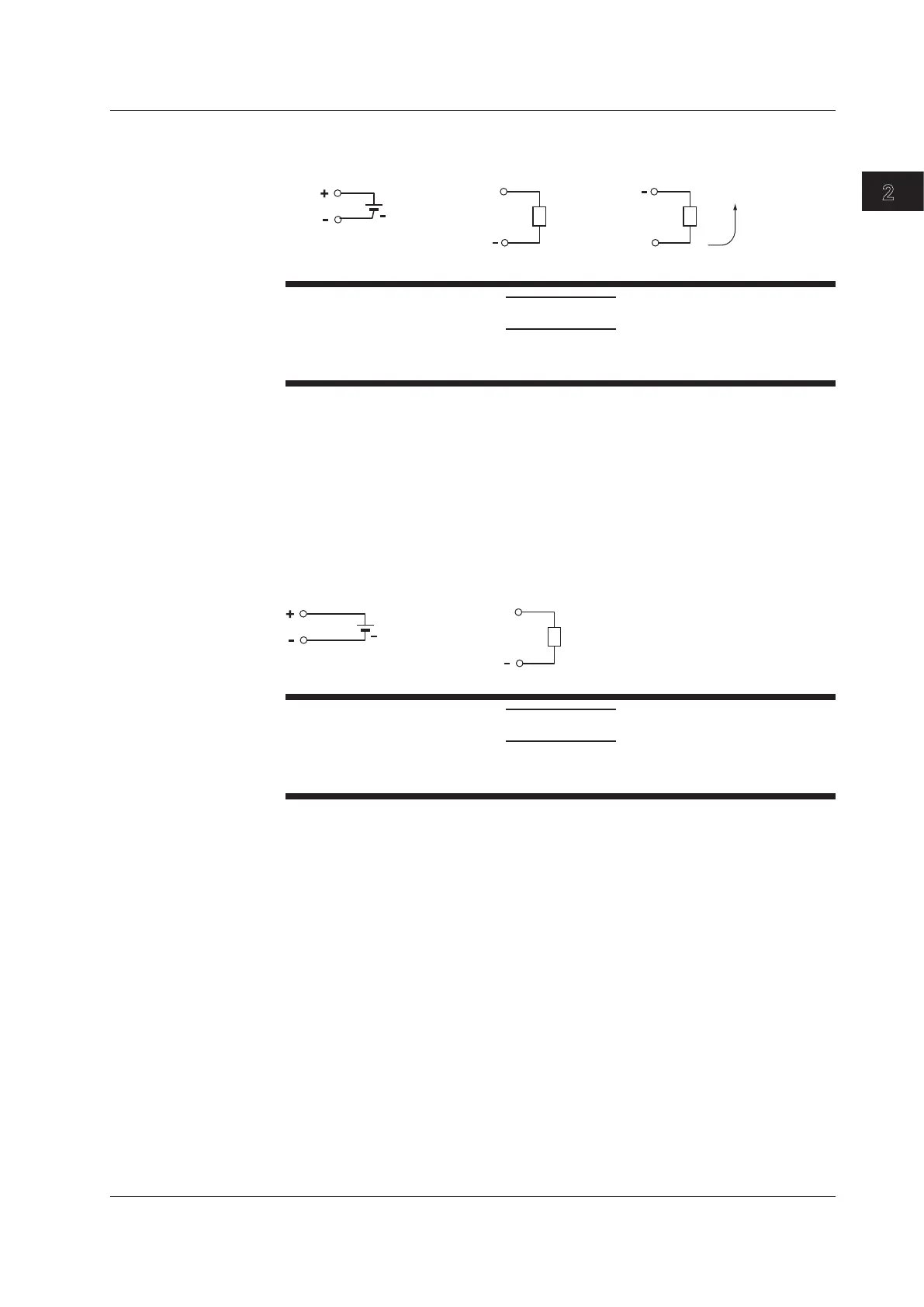
Wiring the Analog Output Modules
External power supply Voltage
V+
Load
+
24 V
power supply
(when using current output)
Direction of
current
Vext
Current
I+
Load
CAUTION
Two power supply terminals are connected internally. Therefore, do not connect a
separate external power supply to them as fire can result.
Main Output Specifications
Terminal type: Clamp, attached and removed in units of 4 channels
Loadimpedance: Voltage5kΩormore
Current600Ωorless
Applicable wire size: 0.08 to 2.5 mm
2
(AWG28 to 12)
Wiring the PWM Output Modules
External power supply Pulse width output
V+
Load
+
4-28 V
power supply
CAUTION
Two power supply terminals are connected internally. Therefore, do not connect a
separate external power supply to them as fire can result.
Main Output Specifications
Output capacity: 1A/ch max, however, 4 A or less total for all modules
*, **
Terminal type: Clamp, attached and removed in units of 4 channels
Applicable wire size: 0.08 to 2.5 mm
2
(AWG28 to 12)
* A 1A current limit circuit is built in to the output circuit. Once the current limit circuit is ON,
the circuit continues to operate unless the external power supply is turned OFF.
** This module has a built-in fuse. The built-in fuse protects against fires or abnormal
emissions of heat due to load shortages or other abnormalities. It does not protect against
damage to internal circuits.
2.4 Connecting the Signal Wires