2-11
IM MX100-01E
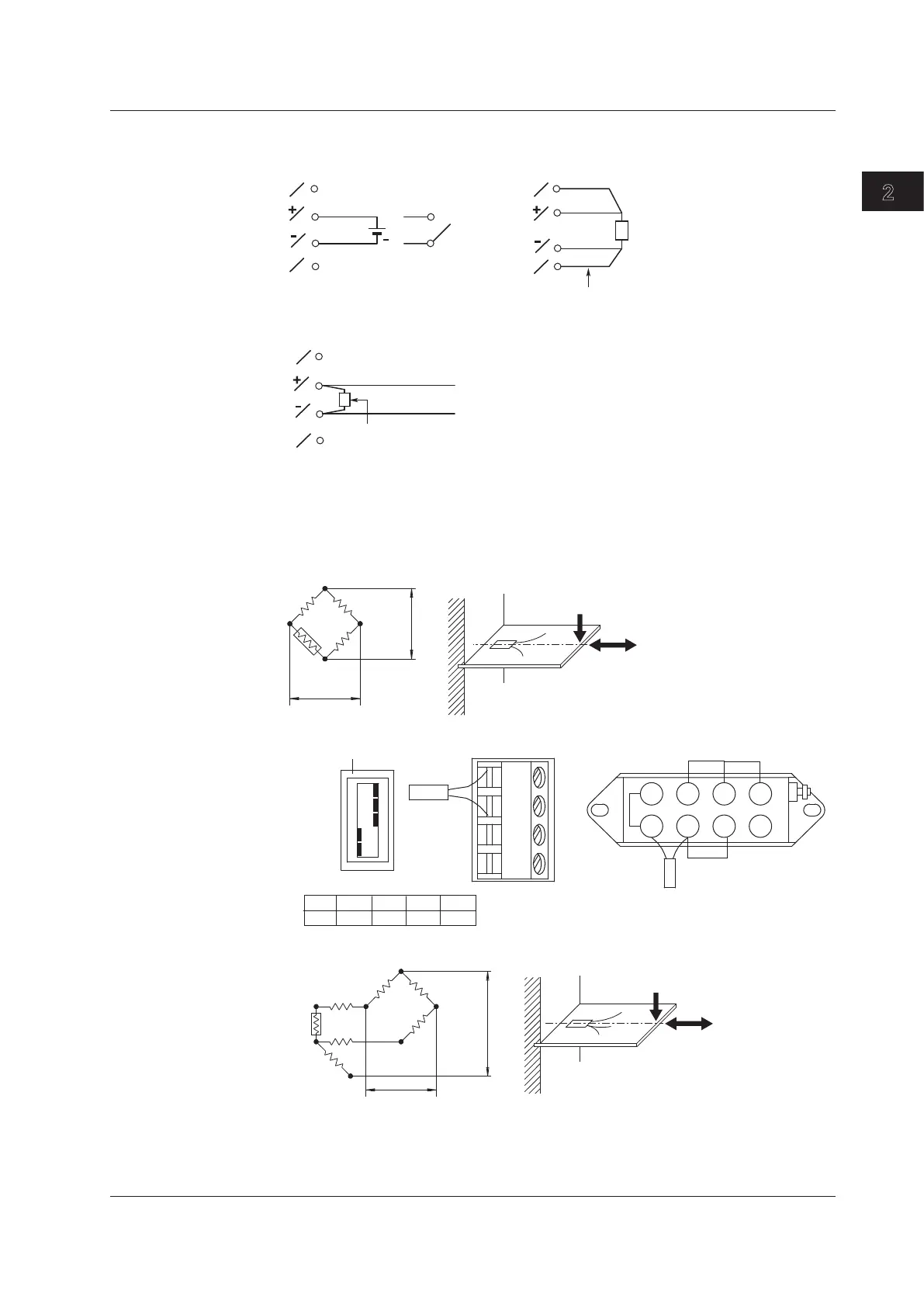
Installation and Wiring
Wiring the 4-Wire RTD Resistance Input Modules
A
B
I
C
A
B
I
C
Votage
Nothing connected to
the I or C terminal
Resistance, RTD
+
Resistance per lead wire of 10 Ω or less
DC voltage
Input
Contact
DC current input
Shunt resistor
Example: For 4 to 20 mA input,
shunt resistance values should
be 250 Ω±0.1%.
–
+
C
I
A
B
• DC voltage input/DI (contact) input • RTD input, resistance input
• DC current input
Teraminal type: Clamp
Applicable wire size: 0.14 to 1.5mm
2
(AWG26 to 16)
Wiring the Strain Input Modules
•
One-Gauge Method
Jumper setting switch
ON
OFF
No.1
No.2
No.3
No.4
No.5
A(+V)
B( L)
C(-V)
D( H)
1 2 3 4
5 6
7 8
-B12, -B35
-NDI
E
e
Rg
R
R
R
Rg
No.1
ON
No.2
ON
No.3
ON
No.4
OFF
No.5
OFF
Rg
Bridge head (319300)
R: fixed resistance
r: resistance value of lead
wire
Rg: resistance value of strain
gauge
e: output voltage from bridge
E: voltage applied to bridge
•
One-Gauge Three-Wire Method
R
R
R
Rg
r
r
r
E
e
R: fixed resistance
r: resistance value of lead wire
Rg: resistance value of strain gauge
e: output voltage from bridge
E: voltage applied to bridge
2.4 Connecting the Signal Wires