1-25
IM MX100-01E
Explanation of Functions
1.9 Functions of the 8-CH, Medium-Speed PWM
Output Module
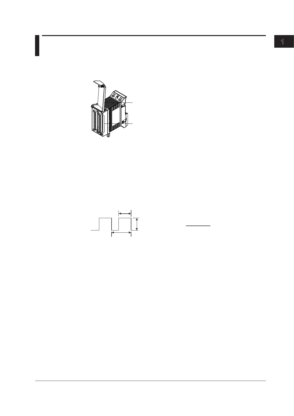
This module is equipped with eight outputs that can output pulse wave duty. A duty pulse
waveform is output according to the specified pulse interval. A pulse interval can be set
for each channel.
Input terminal (clamp terminal)
Terminal cover
Output Type
Transmission output: Outputs a duty pulse waveform corresponding to the
measurement computation results of the input channel specified on
the same unit.
Command output: The specified value is output based on the data sent from the PC
software. Transmission output of computation channel data or of
data from separate units is possible.
Output Waveform
Pulse interval
Output width
External
power supply
voltage
Duty=
Output width
Pulse interval
×100 [%]
Pulse Interval
1 ms-300 s (can be set channel by channel)
However,
1 ms interval setting rng: 1 ms to 30.000 s Can be set in units of 1 ms
10 ms interval setting rng: 10 ms to 300.00 s Can be set in units of 10 ms
Output Update Interval
100 ms (minimum). It is not synchronized to the measurement interval.
Output Range
0.000%to100.000%
Operation When Errors Occur upon Startup
See section 1.10.