2-21
IM MX100-01E
Installation and Wiring
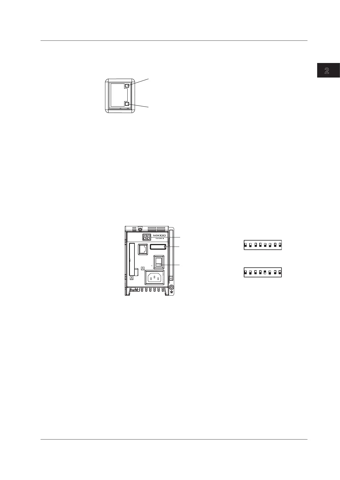
Checking the Communication Status
You can check the status on the two LEDs at the upper-right and lower-right of the
Ethernet port.
ETHERNET
10BASE - T
100BASE - TX
LINK LED
Illuminates in orange when the link between
the MX100 and the connected device is
established and communication is mutually possible.
ACT LED
Illuminates in green when
transmitting/receiving packets.
Initializing the Settings
The dip switch on the main module is used to initialize the settings including the IP
address assigned to the MX100.
1. Turn OFF the power to the MX100.
2. Turn dip switch 5 of the main module OFF.
3. Turn ON the power to the MX100.
The 7-segment LED indicates the self-test operation at power up (see page 1-
8), and then displays bF.
4. Check the status of step 3, then turn the power OFF.
5. Turn dip switch 5 back ON.
Check that the settings have been initialized (using the MX100 Standard
Software, for example).
Power switch
7-segment LED
Dipswitches
DATA
ACQUISITION
UNIT
ETHERNET
POWER
10BASE - T
100BASE - TX
100 - 240V AC
Do not operate without reading safety precaution in users manual.
70VA MAX
50/60Hz
SW
ON
1 2 3 4 5 6 7 8
ON
1
2
3
4
5
6
7
8
ON
1
2
3
4
5
6
7
8
• Normal setting
• Turn switch 5 OFF
Remove the cover when
manipulating the dipswitches.
2.6 Connecting the Ethernet Cable