2-5
IM MX100-01E
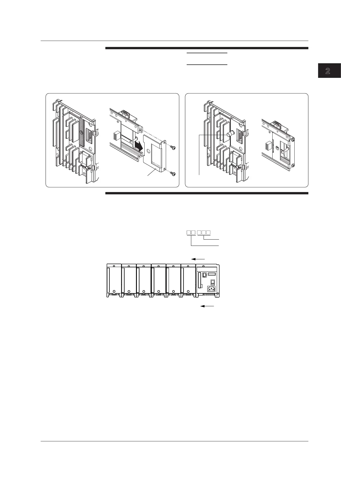
Installation and Wiring
CAUTION
When attaching the main module (conventional model) to the base plate, first
remove the two screws from the base plate and remove the BRACKET, then attach
the main module (conventional model) to the base plate.
BRACKET
Base plate
Main module (conventional model)
Base plate
Main module (reworked model)
Pin protector stud
Attachment Positions and Channel Numbers
The figure below shows how the channel numbers are identified on the PC.
MX100
0
1
2
3
4
5
Slot number
001 to 010
011 to 020
021 to 030
031 to 040
041 to 050
051 to 060
Channel number in the unit**
Representation of channel numbers:
Channel numbers in a unit (001 to 060)
Unit number (00 to 19)
** The last one digit on a 4-channel module
is 1 to 4.
* When connecting to the module
using the MX100 Standard
Software, the number is
fixed to 00.
2.3 Attaching the Modules