3-1
IM MX100-01E
Troubleshooting and Maintenance
Chapter 3 Troubleshooting and Maintenance
3.1 Error Display on the 7-Segment LED and
Corrective Actions
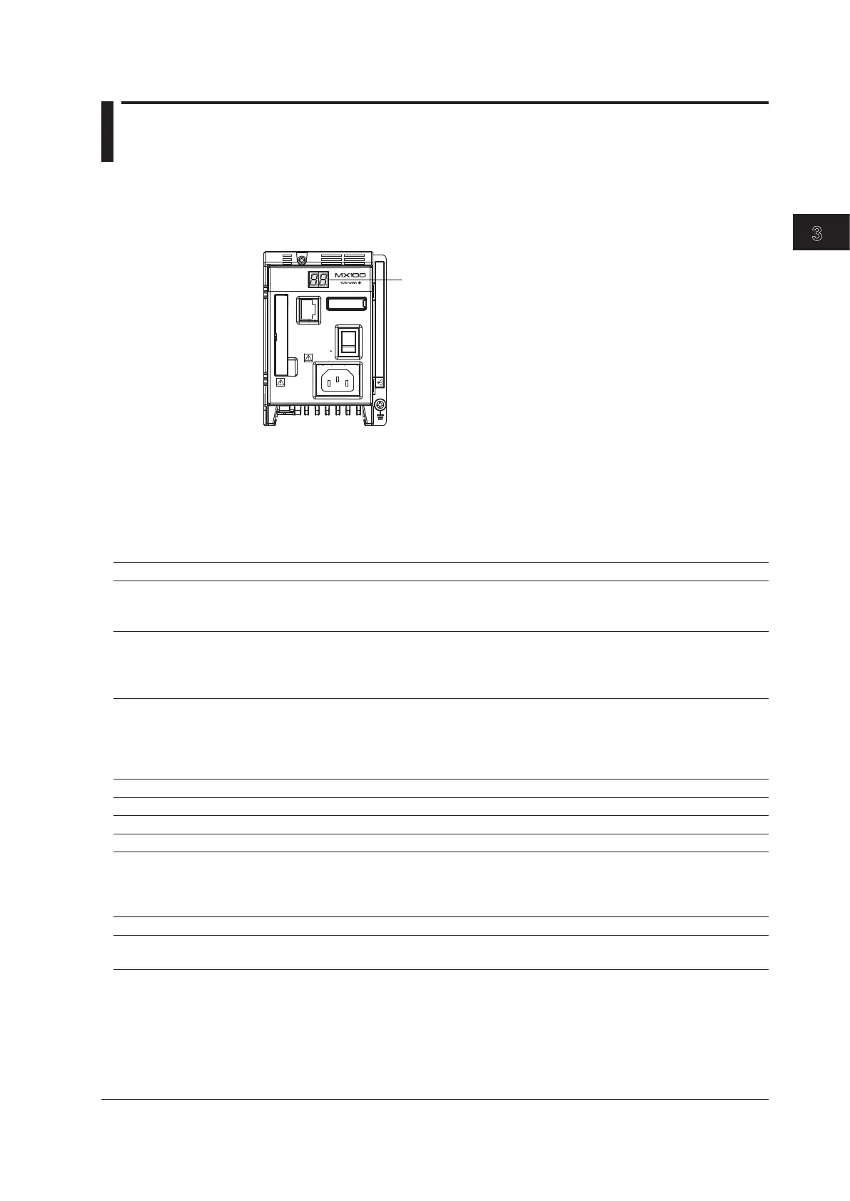
The main module has a two-digit 7-segment LED as shown in the figure below. The
7-segment LED displays the system status. This section describes the displays on the
7-segment LED when errors occur on the system and their corrective actions. For normal
displays other than errors, see pages 1-8 and 1-9.
7-segment LED
DATA
ACQUISITION
UNIT
ETHERNET
POWER
10BASE - T
100BASE - TX
100 - 240V AC
Do not operate without reading safety precaution in users manual.
70VA MAX
50/60Hz
SW
ON
1 2 3 4 5 6 7 8
If servicing is necessary, or if the instrument is not operating correctly after performing
the corrective actions below, contact your nearest YOKOGAWA dealer.
Errors at Power ON
The left and right digits of the 7-segment LED display “b” and an error code, respectively.
The LED illuminates.
Probable Cause Corrective Action Ref. Page
The display is b* (where * is any character Turn OFF the power, remove the CF card, turn ON all 2-24
other than F). The dip switch settings are dip switches, and power up again. If the situation does not
not correct. change servicing is required.
The display is bF. Powering up in setup reset mode. Turn OFF the power, turn 2-21
The dip switch settings are not correct. ON all dip switches, and power up again. Since all settings
such as the IP address are initialized, reconfiguration is
necessary.
System Errors
The left and right digits of the 7-segment LED display “F” and an error code, respectively.
The LED illuminates.
Display Probable Cause Corrective Action Ref. Page
F0 System ROM error. Servicing required. -
F1 SRAM error Servicing required. -
F2 EEPROM error Servicing required. -
F3 Error in the internal battery of the Servicing required. -
main module. However, this error is also displayed immediately after
the battery is replaced.
If this happens, power-cycle the MX100.
F4 Ethernet controller error Servicing required. -
F5 Internal data error Servicing required. -
(only when the /DS option is enabled)