3-7
IM MX100-01E
Troubleshooting and Maintenance
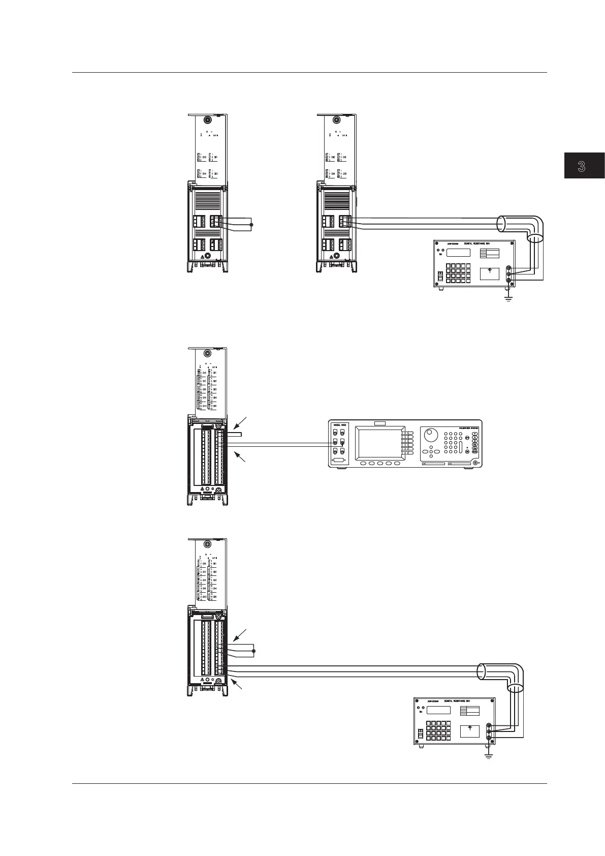
• When calibrating the RTD range of the 4-CH, High-Speed Universal Input module
100Vpk MAX TO
250V MAX CH TO CH
600V MAX TO
100Vpk MAX TO
250V MAX CH TO CH
600V MAX TO
H
L
G
Resistance standard
Input terminal Input terminal
Short
Make the resistance of
three lead wires equal.
When calibrating 0 Ω When calibrating a range other than 0 Ω
* Carry out calibration for each input
terminal.
b
A
B
b
A
B
• When calibrating the DC voltage range of the 10-CH, Medium-Speed Universal Input
module
100Vpk MAX TO
120V MAX CH TO CH
600V MAX TO
Hi
Lo
Input terminal of CH2
Short the input terminal of CH1 (apply 0 V)
+
–
+
–
DC voltage/current standard
• When calibrating the RTD range of the 10-CH, Medium-Speed Universal Input module
b
A
B
b
A
B
100Vpk MAX TO
120V MAX CH TO CH
600V MAX TO
H
L
G
Short the input terminal of CH3 (connect 0 Ω)
When calibrating the RTD (1 mA) 600 mV range,
connect 300 Ω to the input terminal of CH5.*
Make the resistance of three lead wires equal.
* When calibrating the RTD (1 mA) 60 mV range, connect 60 Ω to
the input terminal of CH6.
When calibrating the RTD (1 mA) 200 mV range, connect 200 Ω
to the input terminal of CH4.
Resistance standard
3.3 Calibration