OPERATION
Axio Imager Illumination and contrast methods Carl Zeiss
M70-2-0020 e 06/2009 430000-7344-001 159
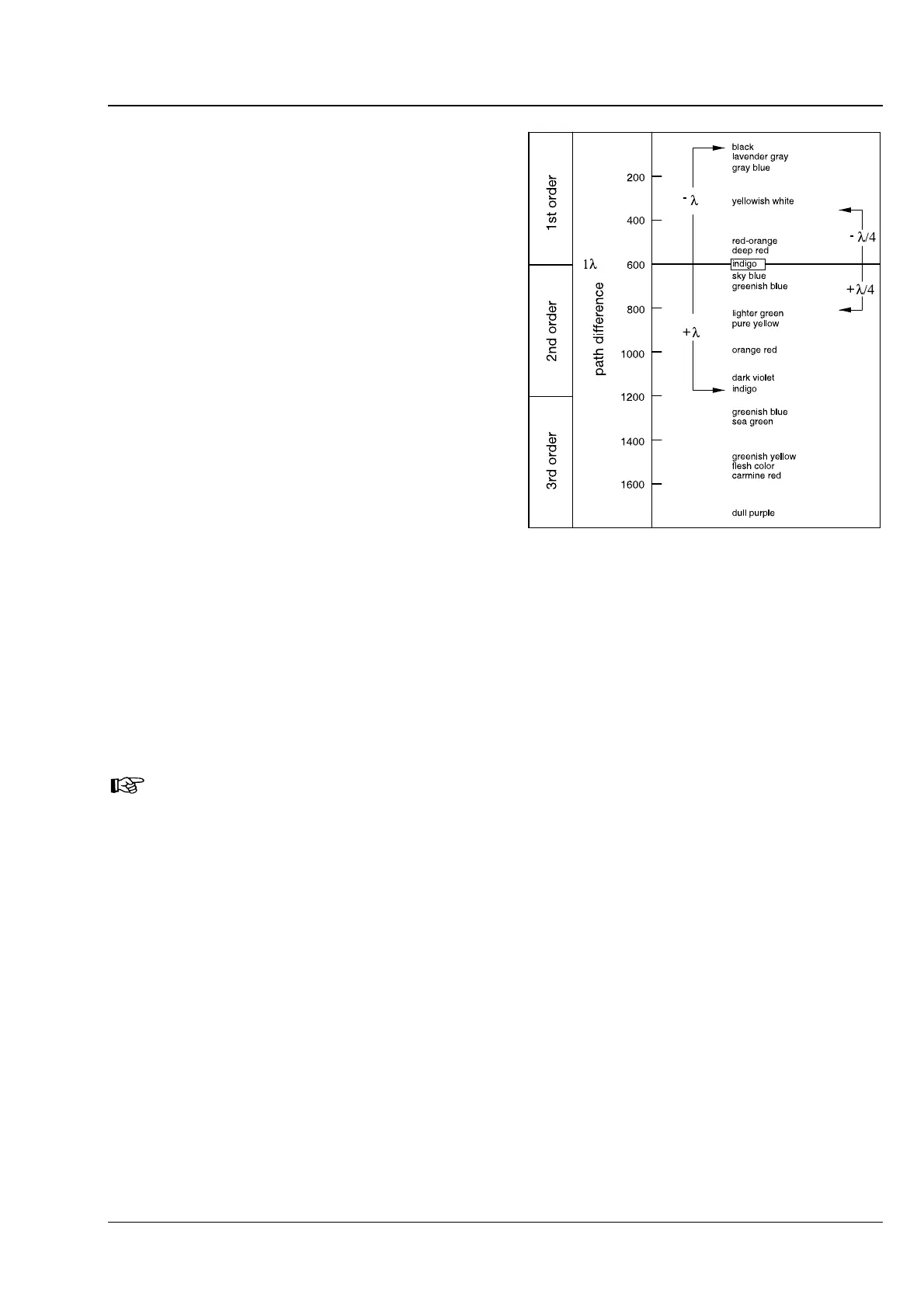
(4) Conclusions
The grayish-white color appearing first in the
bright position in the above example (
4-123/1)
corresponds to a path difference of 150 nm
according to the Michel-Lévy color chart (Fig.
4-124).
When the compensator λ is brought into the light
path, the non-birefringent "surroundings" of the
synthetic fiber appear in a dark red color, which
corresponds to the path difference of the
compensator of 550 nm (1
st
order interference
color for the path difference of 550 nm
corresponds to 1 λ).
If the vibration direction (n
γ
or n
γ'
) of the
birefringent specimen to be examined is parallel to
the principal vibration direction (n
γ
) of the
compensator λ, i.e. in NE-SW direction, the path
difference of the specimen (e.g. grayish-white:
150 nm) and the path difference of the compen-
sator λ (red: 550 nm) add up. This results in a color
change of the specimen from grayish white to
greenish-blue (resulting path difference = 700 nm).
If the vibration direction of the specimen to be examined is perpendicular to the principal vibration
direction of the compensator λ, i.e. in NW-SE direction, the path difference of the specimen (e.g. grayish-
white: 150 nm) is subtracted from the path difference of the compensator λ (red: 550 nm). In this case,
the interference color of the specimen visibly changes from grayish-white to orange (resulting path
difference = 400 nm).
Color charts according to Michel-Lévy are available under Cat. No. 42-312.
Fig. 4-124 Schematic diagram of the color
charts according to Michel-Lévy