REQUIRED PARTS AND TOOLS
Page 9
3.0 REQUIRED PARTS AND TOOLS
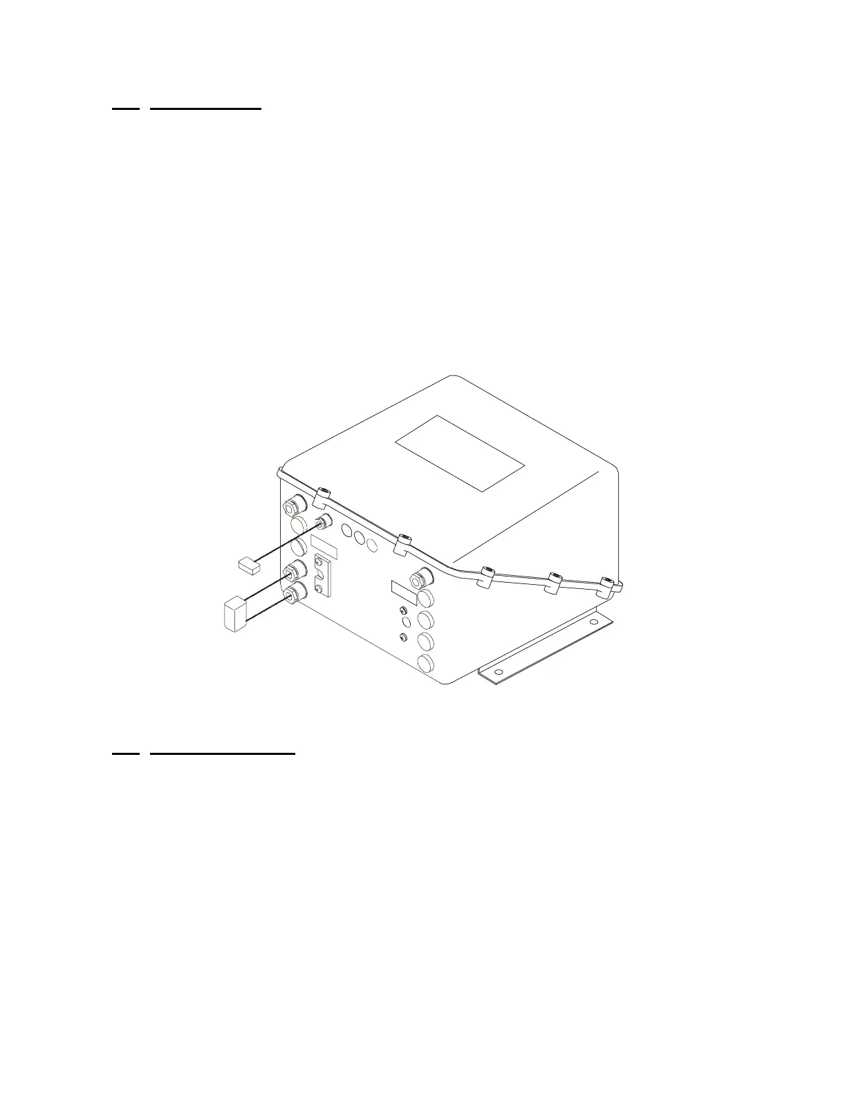
3.1 PROCESSOR
One Processor required per engine (refer to the System Drawing in
Appendix C)
Mounting Hardware is installer supplied.
Included with the Processor:
•Wago Tool
• Anti-Static Wrist Strap
•Spare Fuse
3.2
CONTROL HEAD
Refer to Appendix A for Control Head Variations and Dimensions
Sheets.
One Control Head required per Station.
Included with the Control Head:
• Gasket (400 Series Control Head only)
•Terminals
• Mounting screws
Figure 4: Control Processor
11336-