PLAN THE INSTALLATION
Page 13
4.0 PLAN THE INSTALLATION
4.1 PROCESSOR(S) LOCATION
Processors are spray proof, but must
not be immersed.
An engine room location of the Pro-
cessor is preferred.
• If the engine room is too small,
locate in any area where it is
accessible for electrical and push-
pull cable connections.
Bulkhead mounting preferred for ease
of access for wiring and adjust-
ments, the Processor can be
mounted in any attitude.
• If the clutch cable is connected to
an I/O drive outside the hull, the
Processor must be two feet
(0,6m) or
more above waterline.
Do not mount the Processor on the engine, to the transmission, or in
any location that will subject it to excessive vibration.
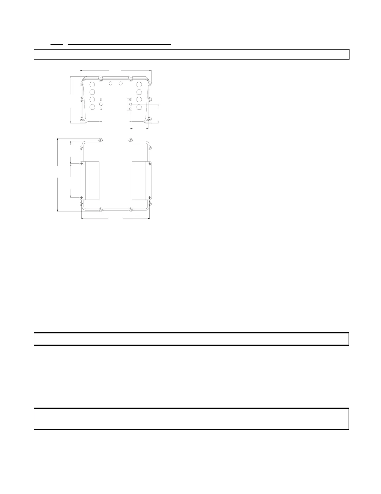
Refer to Figure 6: for Processor dimensions.
Locate Processor(s) away from heat sources, such as engine exhaust
manifolds. Allow 4 feet
(1,2m) of clearance, or more, between the
Processor(s) and such heat sources.
Do not mount close to gas engine ignition systems, alternators, or
electric motors. Allow 4 feet
(1,2m) of clearance between the Pro-
cessor and alternators or electric motors.
The Processor’s mounting feet must be connected to the vessel’s
bonding system.
NOTE: Read the Warranty in Appendix A. Improper mounting location may cancel warranty.
Figure 6: Control Processor Dimensions
10.71
272mm
2.69
68,3mm
6.70
(170,2mm)
2.70
(68,6mm)
3.20
(81,3mm)
10.40
(264,2mm)
4.75
(120,7mm)
10.25
260,4mm
11000-MS569
CAUTION: Electro-magnetic fields can influence ClearCommand’s electronic circuits.
CAUTION: It is mandatory that the Processor DC negative is bonded (connected) to the vessel
bonding system. See Appendix A Bonding Section.