INSTALLATION
Page 18
.
5.4 CONTROL HEADS
See Appendix A Control Head Dimensions and Variations for location
of cutout and mounting holes for the Control Heads used with this
application. Refer only to the following Sections that relate to the
Control Heads used.
5.4.1 Mounting
400 Series Control Head:
A) Use the template supplied in Appendix A and drill the screw holes
and the corner cutout holes.
B) Saw between the corner cutout holes.
C) Check that the four mounting screws will start into the Control
Head.
D) Remove the Control Head.
E) Strip the adhesive cover from the gasket and apply the adhesive
side to the console.
700 Series Control Head:
A) Drill the screw holes and the cable holes.
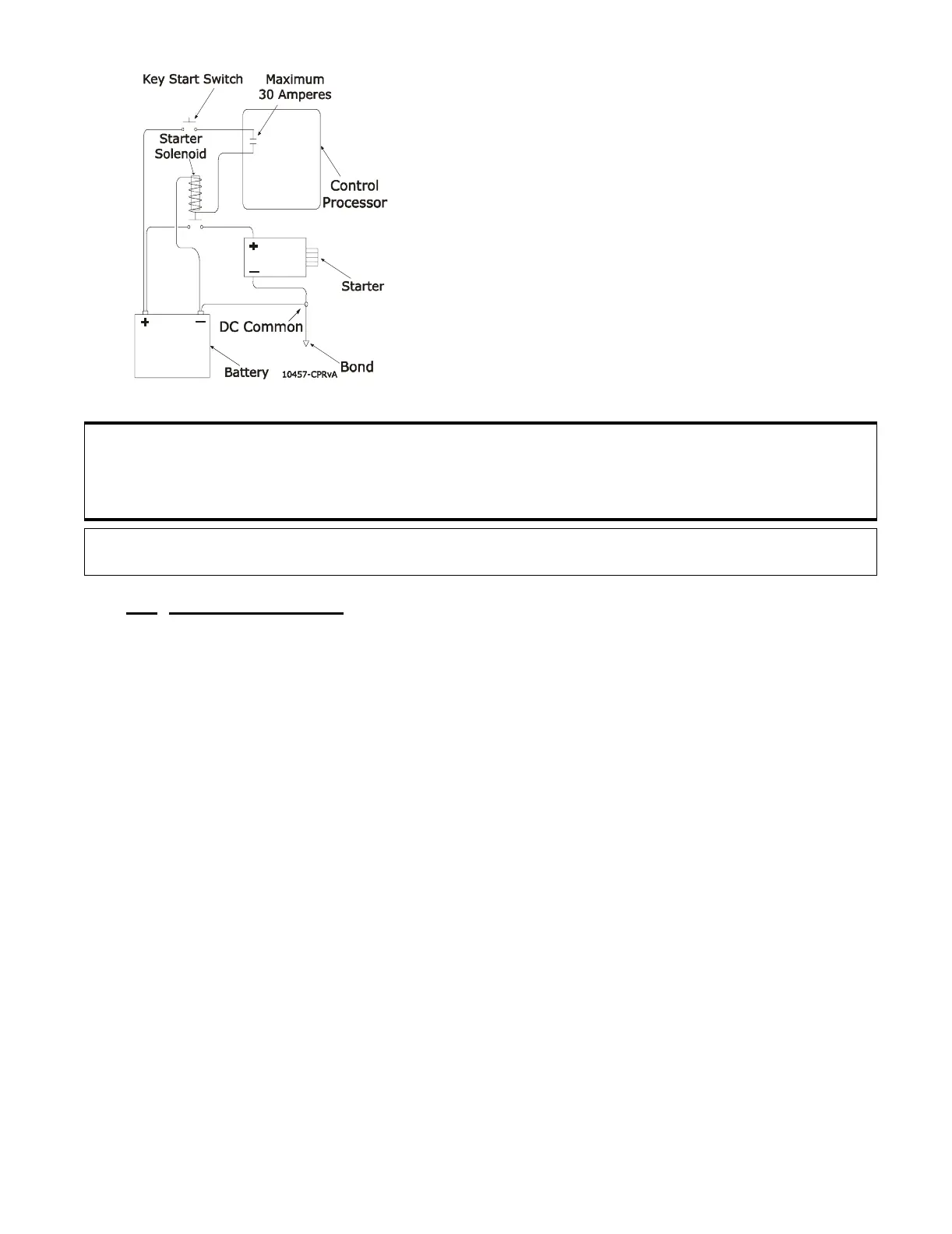
B) Run the two-conductor start interlock
cable through the watertight cable grip.
C) Strip insulation off of each wire 3/8-inch
(9,5mm), then install crimp terminals.
D) Connect the two-conductor cable as indi-
cated on the Drawing in Appendix C.
E) Feed through a little slack cable and
tighten the cable grip
F) Tie wrap the start interlock cable to the
Processor frame
Figure 9: Start Interlock Connections
CAUTION: The most common source of trouble is loose wiring connections. Verify wiring connec-
tors are properly crimped and cannot be pulled out. Crimps and connections must be
made to the wire, not to the wire insulation. Verify all screwed wire connections are
secure.
NOTE: Repeat for all Processors. Ensure all connections at the Processor are as indicated on the
Drawing in Appendix C.