INSTALLATION
Page 20
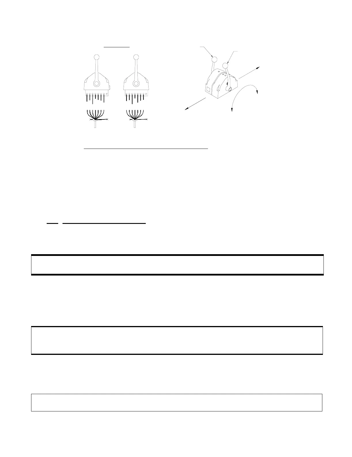
Refer to Figure 10:.
For single lever Control Head Stations
that have the user facing aft and
the single Control Head lever on the user’s right, reverse connections 5
and 7.
5.4.4 700 Series Control Head Only
When cable connections are complete, replace the bottom cover with the
six screws removed earlier. Ensure seal is in place.
5.5 ENGINE STOP SWITCH
The Installer supplies the Stop Switches. Refer to the information sup-
plied with the Stop Switches for installation.
5.5.1 Synchronization (Multi-Engine Only)
For Multi-Engine Applications, the Processors need to be interconnected
with a Serial Communication Wire Harness as demonstrated on the Draw-
ing in Appendix C.
A) Plug the Serial Communication Harness to the Serial Harness pig-
tail of a Processor.
B) Run the harness cable to the next Processor.
Figure 10: Aft Facing Control Heads
WARNING: Each Station must have some method to stop the engine. Refer to CFR46, SEC.
62.35-5 and ABYC P-24.5.8..
CAUTION: When connecting the plugs, ensure that the release buttons are depressed and held
until plug is fully connected. To disconnect the plugs, the release buttons MUST be
depressed and held until plug is disconnected. Refer to Figure 8:, page 12.
NOTE: When installing the harness cable, support the cables using clamps or straps not more
than 18 inches (0,5m) apart, unless contained in a conduit.
Side View
Stbd
Port
Lever for
Starboard
Propulsion
Control
Lever for
Port
Propulsion
Control
Fore
Aft
Ahead
Astern
1 2 3 4 5 6 7 8
1 2 3 4 5 6 7 8
Black
Brown
Red
Orange
Yellow
Green
Blue
Black
Brown
Red
Orange
Blue
Green
Yellow
Violet
Violet
10987