INSTALLATION
Page 16
5.3 PROCESSOR CONNECTIONS AND SET-UP
5.3.1 Processor Station Connections
A) Insert cable through the appropriate watertight cable grip.
B) Strip the PVC jacket and shielding back approximately 3 inches
(75mm).
C) Stagger wire lead length to match the correct Station terminal strip.
D) Strip the wire insulation 3/8-inch
(9,5mm) on each wire.
H) Connect the shielding drain wire (bare wire) to Terminal 8 on the sta-
tion terminal strip.
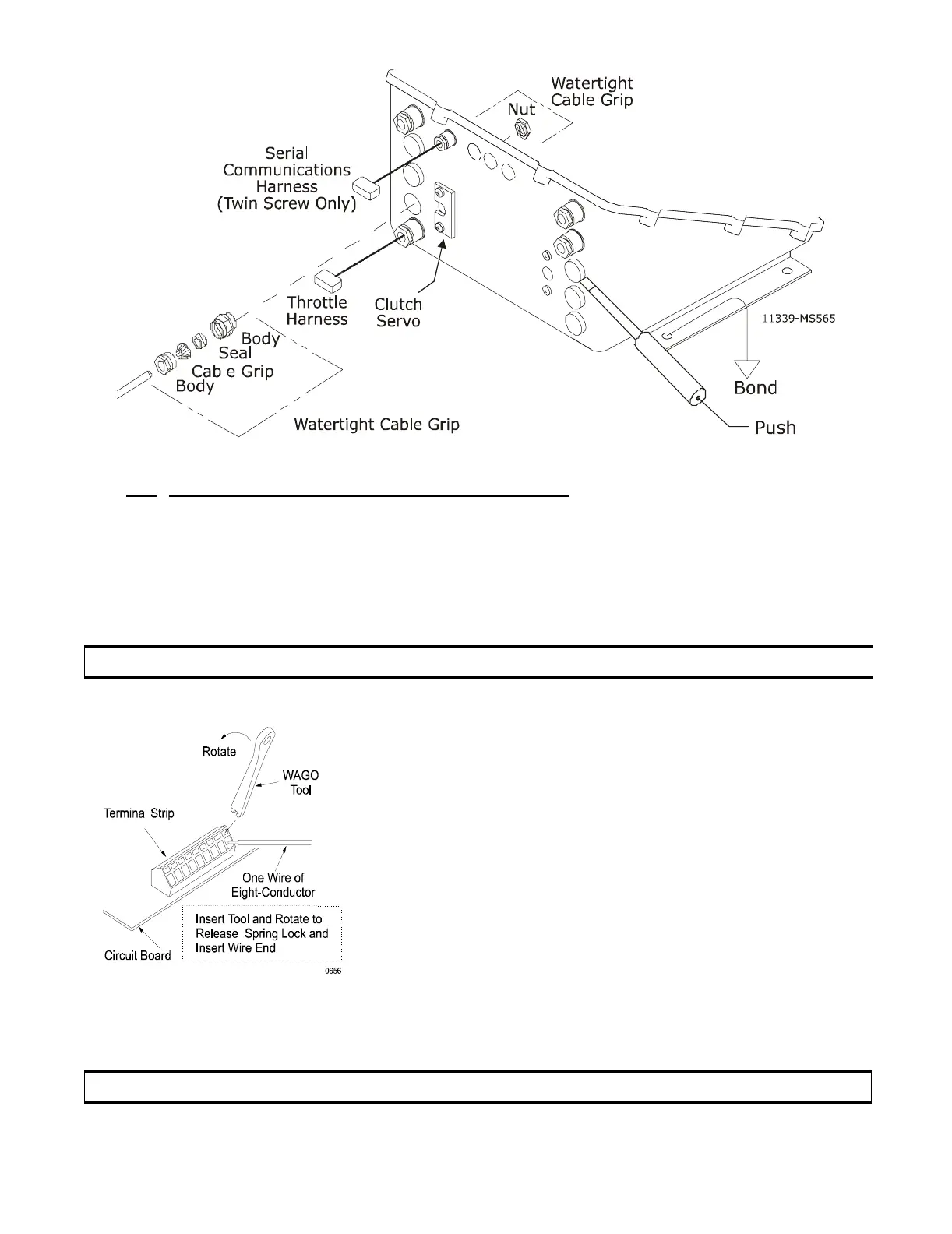
Figure 7: Plug Removal and Cable Grip Installation
CAUTION: Wire leads must not touch frame.
E) Locate the WAGO Tool that is taped to the relay on
the circuit board in each Processor. Use this tool to
depress the spring lock to release the Jumper from the
Station terminal strip.
F) Use the WAGO Tool to depress the spring lock for
the individual wire connections to the terminal strip.
(Refer to Figure 8:)
G) Connect colors to the station terminal strips as shown
on System Drawing in Appendix C.
Figure 8: Terminal Connection
CAUTION: The shielding drain wire MUST NOT touch any other components.