INSTALLATION
Page 22
C) Loosen the remaining screw and swing the cable retainer clip away
from the entry hole.
D) Insert the push-pull cables
through the entry hole.
E) When the push-pull cable end is visible within the Processor interior,
reinstall the Number 10-32 jam nut.
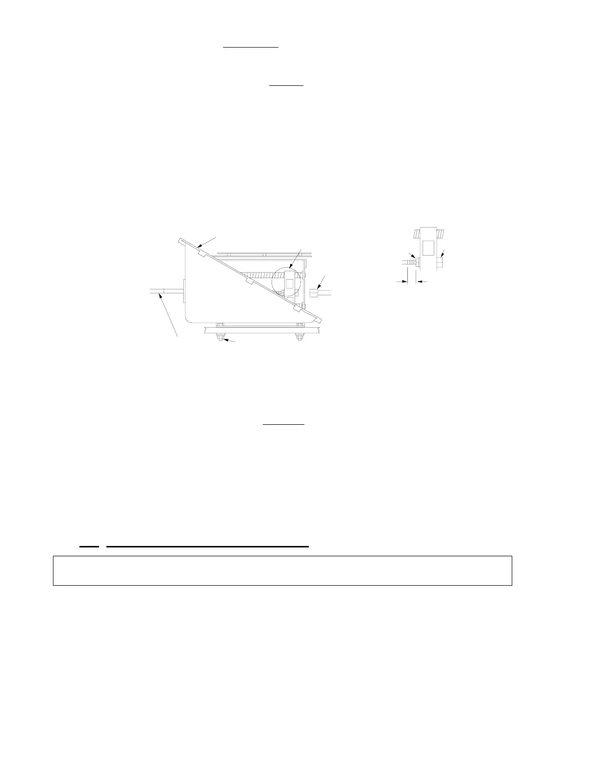
F) Connect the push-pull cable to the hex nut (See Figure 12:, Detail I).
Use a 7/16-inch socket to turn the hex nut onto the cable rod end until
there is approximately 5/16 inch
(7,9mm) of thread showing beyond the
jam nut.
G) Tighten the jam nut to the hex nut.
H) Reinstall the cable retainer clip to secure the push-pull cable to the Pro-
cessor housing.
I) Run the push-pull cable to the transmission. Insure the correct push-
pull cable is ran to the correct selector lever. Refer to the System
Drawing in Appendix C and to Figure 8:, page 17.
J) Do not connect the push-pull cable at this time.
5.7 MAIN ENGINE SPEED CONTROL
• Ensure the correct Wire Harness is selected for the Engine Selec-
tion required for this System.
• Refer to the System Drawing Notes in Appendix C for the Engine
Selection available.
Figure 12: Push-Pull Cable Connection
NOTE: Ensure all Processors are set-up using the same Jumper 6 Throttle Profile, Wire
Harness, and Set-up Engine Selection.
Push-Pull Cable
(not Supplied)
1/4" Mounting Hardware
(not Supplied)
7/16" Socket
0658
See Detail I
Control Processor
Housing
Jam Nut
Tighten
Hex
Nut
5/16"
(8mm)
Detail I