ADJUSTMENT AND TESTS [AT DOCK]
Page 36
7.3.1 Neutral Position
Adjust the clutch cable ball joint at the transmission to match the clutch
selector lever in the Neutral position.
Leave the clutch cable disconnected.
7.3.2 Ahead Position
H) If cable needs adjustment rotate Potentiometer R7 clockwise to
achieve the required clutch cable travel for Ahead. (Refer to the Sys-
tem Drawing for location of R7)
I) Store the value that has been set by following Section 6.1.6, page 24.
7.3.3 Verify Neutral, Ahead, and Astern
A) Verify all three positions by moving the Control Head lever: Ahead,
Neutral, and Astern.
NOTE: The push-pull cable must form a right angle (90 degrees) with the clutch selector lever in
the Neutral position.
A)Move the clutch selector lever on the transmission from the
Neutral position to the Ahead position.
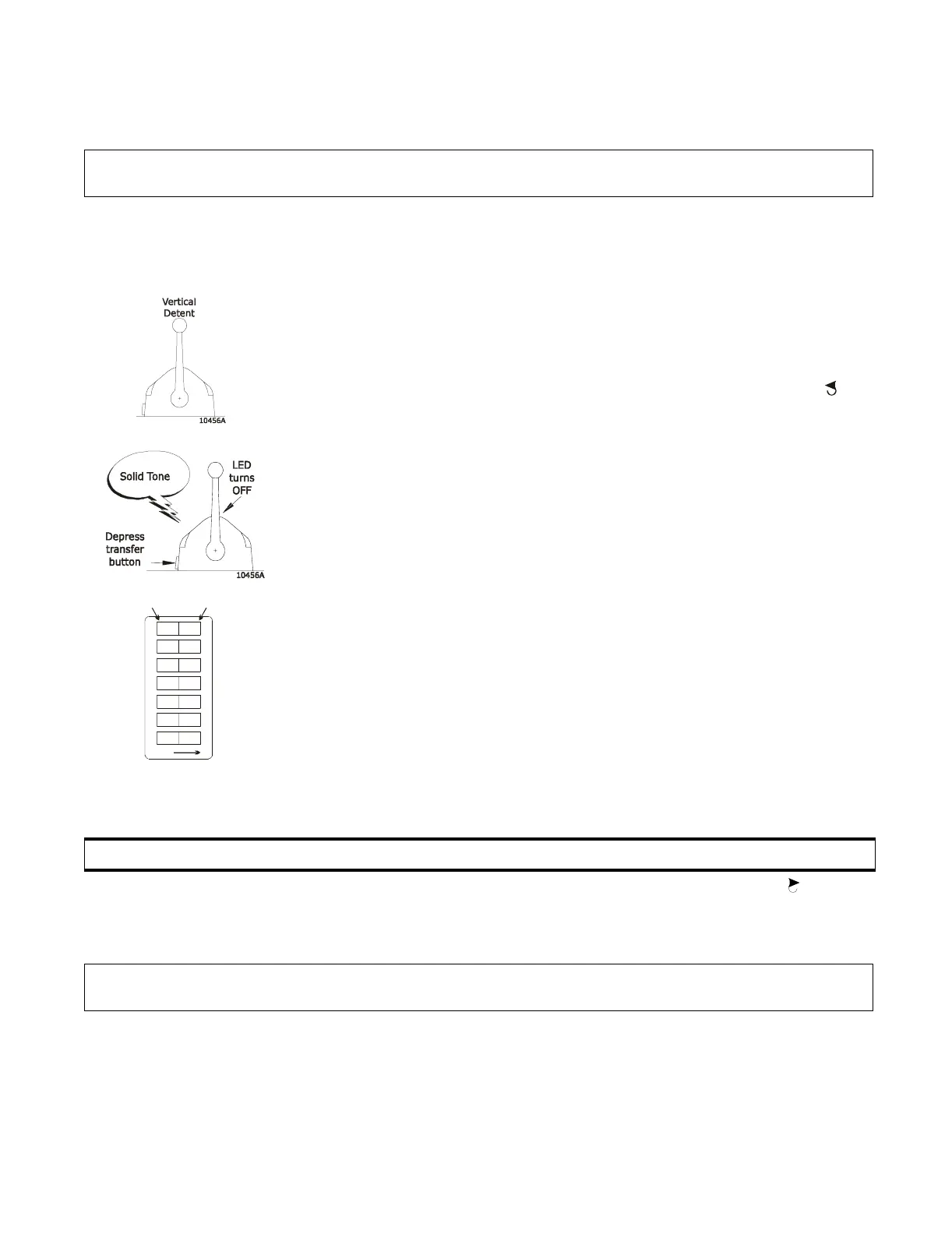
B) Leave the Control Head lever in the vertical detent.
C) Ensure Potentiometer R7 is in the fully counter clockwise
position.
Figure 25: Dip Switch
Setting Clutch Cable Travel
D) Enable Set-up Mode by following Section 6.1.5, page 23
E) Press the transfer button at the remote station that will be used
during clutch set-up.
• Verify a tone is heard when depressing the transfer button.
• The Control Head LED will not be lit, but the Control Head
will be active for set-up procedures
F) Place the appropriate Dip Switches On to allow adjustment to
the Clutch Travel.
• Refer to Figure 25: for the Dip Switch settings.
G) Place the Control Head lever into the Ahead detent position.
• The push-pull cable will move to the Ahead position. If
cable does not move in the correct direction for ahead,
ensure Jumper 4 on the Main Circuit Board is on the correct
setting.
CAUTION: The Processors are shipped with the Clutch Travel set for maximum cable movement.
NOTE: Only the Ahead cable travel is adjusted. The Astern cable travel will be the same as the
Ahead cable travel.
0657-600
12
34567
OFF
To change, use a
small screwdriver.
PUSH DOWN
FOR ‘ON’
PUSH DOWN
FOR ‘OFF’
OFF
OFF
OFF
OFF
OFF
ON
ON