Page 9
ZF Mathers, LLC
1415 Pacific Drive
Burlington WA 98233-3103 U.S.A.
800-546-5455 / 360-757-6265
Fax: 360-757-2500
MMC-310 Rev.D 6-01
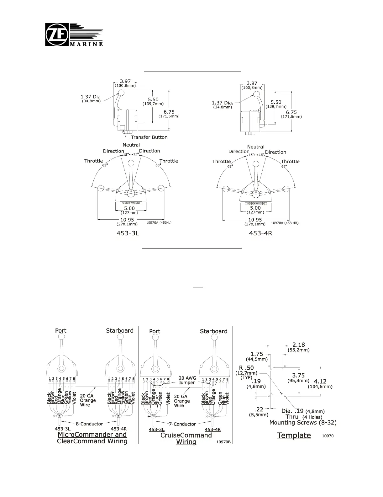
Standard Cable Connections
Select the desired mounting locations and drill holes per template. Run cables between Actuator/
Processor and Control Head. At the Control Head, strip back the PVC cover on the shielded cable
approximately 2" (50mm). Strip and cut off the shielding and drain wire flush with the end of the
PVC cover (the drain wire at the Control Head is not connected to ground). Strip 3/8" (9,5mm) insu-
lation off each wire. Twist the individual strands of the wires to minimize fraying. Crimp a lock-
ing fork terminal (included with each Control Head) to each of the conductors. Make connections
to the Control Heads for MicroCommander, ClearCommand, and CruiseCommand as shown
below.
464-4 Control Head Sheet