Page 8
E) Strip 3/8" (9,5mm) insulation off each wire.
F) Twist the individual strands of the wires to minimize fraying.
G) Crimp a locking fork terminal (included with each Control Head) to each of the con-
ductors.
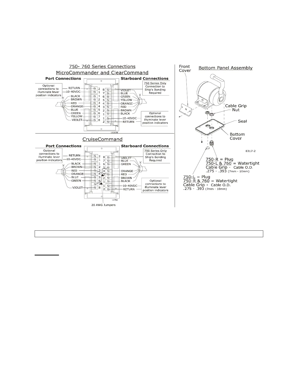
H) Make connections to the Control Head as shown below for MicroCommander,
ClearCommand, and CruiseCommand Systems.
I) When connections are complete, replace the bottom cover to the bottom of the Control
Head housing.
J) Tighten watertight cable grip(s).
Mounting
A) Select mounting location and drill mounting holes as shown in the template on the front
page.
B) Remove front cover from the Control Head
C) Mount Control Head with supplied hardware.
D) Replace front cover when mounting is complete.
NOTE:On 750 Series Control Heads use one of the bottom cover screws to connect to the ship’s bonding system.