INSTALLATION
Page 21
C) Plug the Serial Communication Harness to the Serial Harness pig-
tail of the Processor.
5.6 PUSH-PULL CABLES
The Processor interconnects with the transmission by push-pull cable
to operate the clutch selector lever. The maximum load rating is 30
pounds force and 3-inches
(7,62 cm) maximum movement of the push-
pull cable.
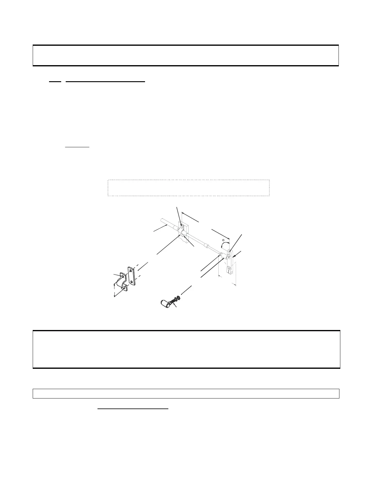
Verify installation of push-pull cable brackets on the transmission. If
the brackets are missing, fabricate brackets as shown in Figure 11:
5.6.1 Push-Pull Connection at Processor
A) Remove the Number
10-32 jam nut and the two rubber seals from the
push-pull cable end that is to connect to the Processor. Discard seals.
B) On the Processor housing, remove one screw from the cable retainer
clip.
CAUTION: Ensure all Processors are interconnected as demonstrated on the System Drawing in
Appendix C.
Figure 11: Universal Mounting
CAUTION: If 43C cable is required for this application, a 43C Cable Conversion Kit is required.
These Kits are available from ZF Mathers, LLC. Refer to Appendix A - 43C Cable
Conversion Kit Manual. Skip Section 5.6.1 and refer to the 43C Cable Conversion Kit
Manual for installation of the 43C Cable.
NOTE: Perform the following steps for 33C Clutch push-pull cable installation.
3/16" Diameter
(4,8mm)
7-3/8"
(187mm)
1/4"
Diameter
(6,4mm)
Selector
lever
2-3/4"
Maximum Movement
(70mm)
Ball Joint
1/4" - 28 UNF Stud
Jam Nut
Shim
Cable Clamp
33C
Cable
1"
(25,4mm)
TYP 7/32"
Diameter
(5,8mm)
90
10246-
Fabricate Bracket to match dimensions shown.