DIP SWITCH SET-UP PROCEDURES
Page 25
6.1.2 Order of Set-up Adjustments
Adjustment settings can be done one right after another or one at a time.
Once a setting has been saved by depressing PB1, adjustment of another
parameter may be started by:
1. Set all the Dip Switches to the Off position.
2. Place the Control Head lever(s) in the vertical position.
3. Ensure Potentiometer R7 is in the fully counter clockwise position.
4. Adjustment of another parameter may be started.
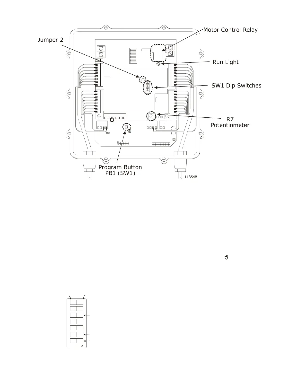
6.1.3 Selecting Dip Switches
Figure 14: Processor Circuit Board Set-up Locations
When switching the Dip Switches ON, select the
switches in the order from Highest to Lowest.
EXAMPLE: Refer to Figure 15:. Throttle Maximum:
SW1-5 select ON 1st,
SW1-2 select ON 2nd,
SW1-1 select ON last
Figure 15: Dip Switch SW1 Setting Example
0657
12
34
5
67
OFF
To cha n
e, use a
small screwdriver.
PUSH DOWN
FOR ‘ON’
PUSH DOWN
FOR ‘OFF’
OFF
OFF
ON
ON
ON
OFF
OFF
First
Second
Last