DIP SWITCH SET-UP PROCEDURES
Page 28
6.2 NUMBER OF SCREWS SELECTION [SINGLE/TWIN, ETC]
Set the SW1 Dip Switches on the Processor Main Circuit Boards using
the following steps:
A)Place the System in Set-up Mode by following Section 6.1.5,
page 26.
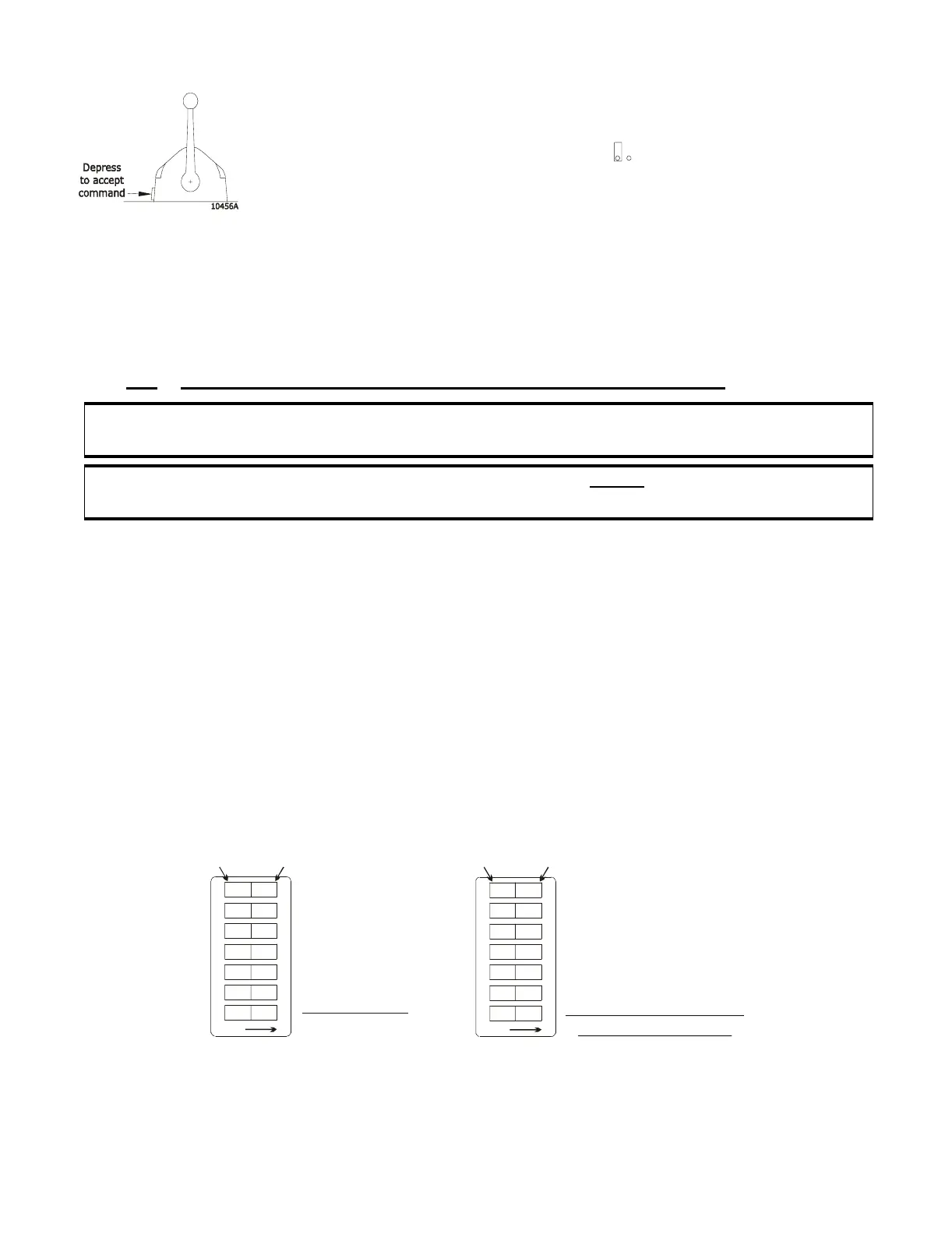
B)Refer to the Figure 18: for the correct Dip Switch setting.
•Refer to Figure 14:, page 25, for the location of the Dip
Switch.
C)Store the value that has been set by following Section 6.1.6,
page 27.
D)If Dip Switch R7 has been used during the Set-up, ensure
R7 is in the fully counterclockwise position.
E)Place Jumper 2 in the Open State .
• A low repetitious rate tone is heard indicating that the Con-
trol System is out of Set-up Mode and no Station is in com-
mand.
F) Take command at a Station.
• The red LED will light; indicating Station is in command
CAUTION: The Number of Screws setting MUST be made before setting the System ID # of each
Processor.
CAUTION:The settings on all Processors Main Circuit Boards MUST be set the same for Twin
Screw or more applications.
Figure 18: Dip Switch Setting Number of Screw5)
0657-600
1
234567
OFF
To change, us e a
small screwdriver.
PUSH DOWN
FOR ‘ON’
PUSH DOWN
FOR ‘OFF’
OFF
OFF
OFF
OFF
OFF
OFF
ON
Single Screw
0657-600
1
2
34567
OFF
PUSH DOWN
FOR ‘ON’
PUSH DOWN
FOR ‘OFF’
OFF
OFF
OFF
OFF
OFF
OFF
ON
Twin Screw (or more)
FACTORY DEFAULT