DIP SWITCH SET-UP PROCEDURES
Page 33
C) Store the value that has been set by following Section 6.1.6,
page 27
6.8
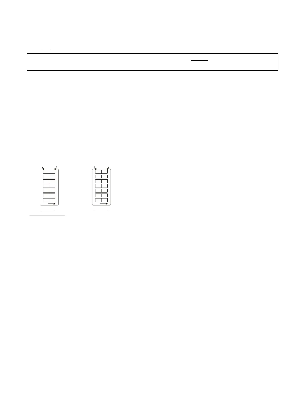
IN GEAR/NEUTRAL DELAY
This feature allows the choice of having Clutch Delay begin counting
down while In Gear or while in Neutral.
The Processors are set at the Factory for In Gear Delay operation.
Set the SW1 Dip Switches on the Processor Main Circuit Boards using
the following steps:
CAUTION: The settings on all Processors Main Circuit Boards MUST be set the same for Multi-
Screw applications.
A)Place the System in Set-up Mode by follow-
ing Section 6.1.5, page 26.
B)Place the appropriate SW1 Dip Switches ON
for In Gear or Neutral Delay.
• Refer to Figure 24: for the Dip Switch set-
tings
C)Store the value that has been set by following
Section 6.1.6, page 27.
Figure 24: Dip Switch Setting In Gear/Neutral Delay
To c hange, u se a
small screwdriver.
0657-600
1
2
3
4
5
67
OFF
FOR ‘ON’
FOR ‘OFF’
OFF
OFF
OFF
OFF
ON
In Gear
FACTORY DEFAULT
0657-600
1
23
4
5
67
OFF
FOR ‘ON’
FOR ‘OFF’
OFF
OFF
OFF
OFF
ON
Neutral
ON
ON
ON
ON