ADJUSTMENT AND TESTS [AT DOCK]
Page 40
H) Store the value that has been set by following Section 6.1.6, page 24.
7.6.2 Throttle Maximum Signal
Change the throttle maximum signal by:
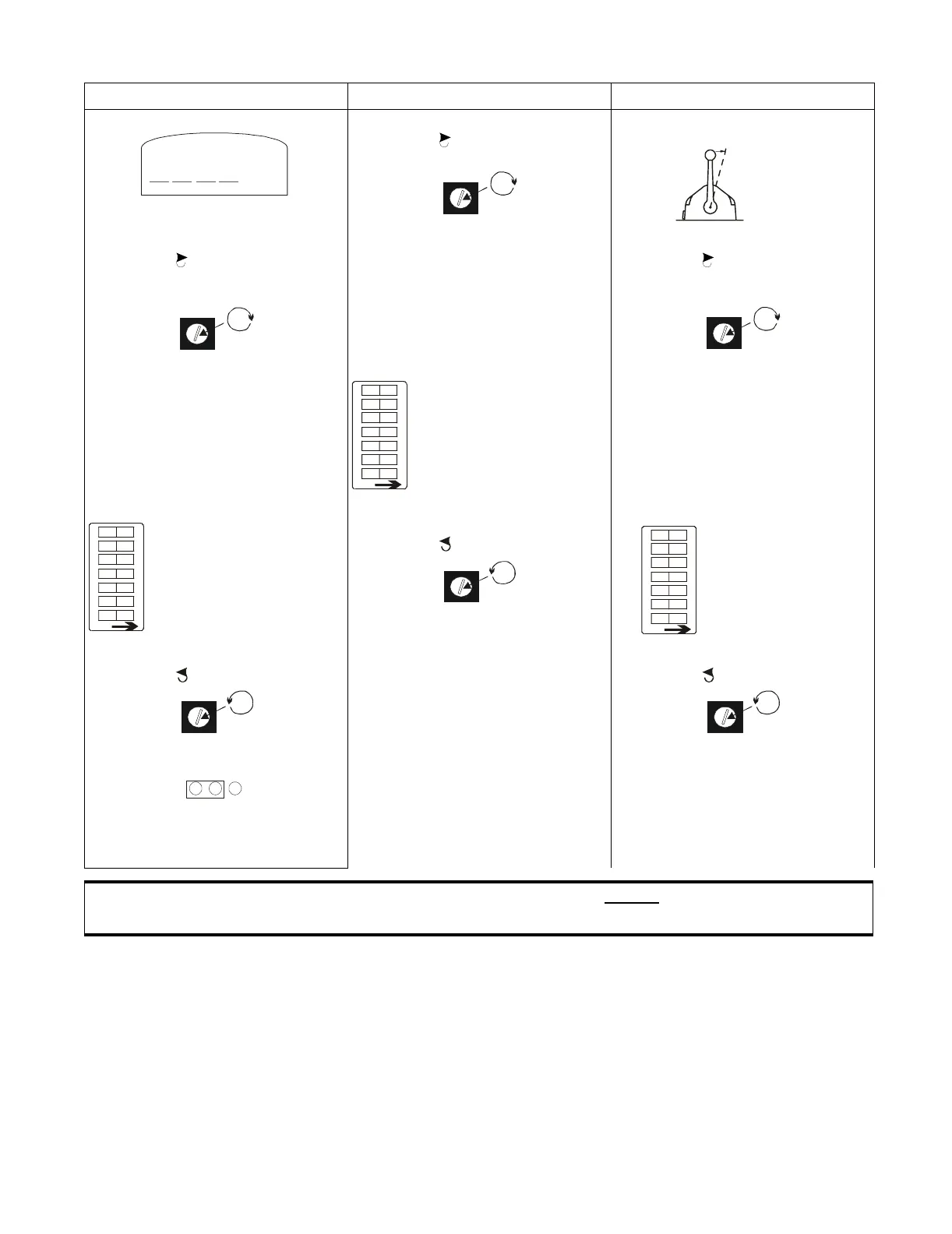
A) Take command at a Station.
B) Leave the Control Head lever(s) in the vertical detent.
PWM (Duty Cycle) Voltage (VDC) Current (mA)
5) Set Multi meter to Duty Cycle setting. 5) Rotate Potentiometer R7 slowly
clockwise until minimum throttle
signal is achieved.
5) Place the Control Head lever into the
Ahead detent position.
6) Rotate Potentiometer R7 slowly
clockwise until minimum throttle
signal is achieved. Refer to Figure 13:,
page 25 for R7 location.
6) Store the value by depressing PB1
located on the Auxiliary Board.
(Refer to Figure 13:, page 25 for
location of PB1)
• The motor control relay will click
once to confirm the value has been
stored.
6) Rotate Potentiometer R7 slowly
clockwise until minimum throttle
signal is achieved. Refer to Figure 13:,
page 25 for R7 location.
7) Store the value by depressing PB1
located on the Auxiliary Board.
(Refer to Figure 13:, page 25, for
location of PB1)
• The motor control relay will click
once to confirm the value has been
stored.
7)Reset all of the Dip
Switches to the Off position
(Run State)
7) Store the value by depressing PB1
located on the Auxiliary Board.
(Refer to Figure 13:, page 25 for
location of PB1)
• The motor control relay will click
once to confirm the value has been
stored.
8) Reset all of the Dip
Switches to the Off position
(Run State).
8) Return Potentiometer R7 fully counter
clockwise .
8) Reset all of the Dip
Switches to the Off
position (Run State).
9) Return Potentiometer R7 fully counter
clockwise .
9) Reconnect the Throttle Wire Harness to
the Throttle Pigtail at the Processor.
9) Return Potentiometer R7 fully counter
clockwise .
10)Replace Jumper 6 on Auxiliary Board
to its original position.
10)Reconnect the positive (+) throttle
signal wire from the governor
11)Reconnect the Throttle Wire Harness
to the Throttle Pigtail at the Processor.
CAUTION: The settings on all Processors Main Circuit Boards MUST be set the same for Twin
Screw (or more) applications.
Table 1: Throttle Minimum Output Adjustments
%
Move To
Ahead Detent
10161
0657-600
1234567
OFF
OF F
OF F
OF F
OF F
OF F
OF F
OF F
0657-600
1234567
OFF
OF F
OF F
OF F
OF F
OF F
OF F
OF F
-
1234567
OFF
OF F
OF F
OF F
OF F
OF F
OF F
OF F
1 2 3