ADJUSTMENT AND TESTS [AT DOCK]
Page 39
Figure 26: Dip Switch
Setting Throttle
Minimum
• The Control Head LED will not be lit, but the Control Head will
be active for set-up procedures.
F) Place the appropriate Dip Switches On to ready the Processor for
adjustment.
• Refer Figure 26: for the Dip Switch settings of Throttle Mini-
mum.
G)Adjust Throttle Minimum Output using the PWM, Voltage, or
Current steps outlined in Ta ble 1:
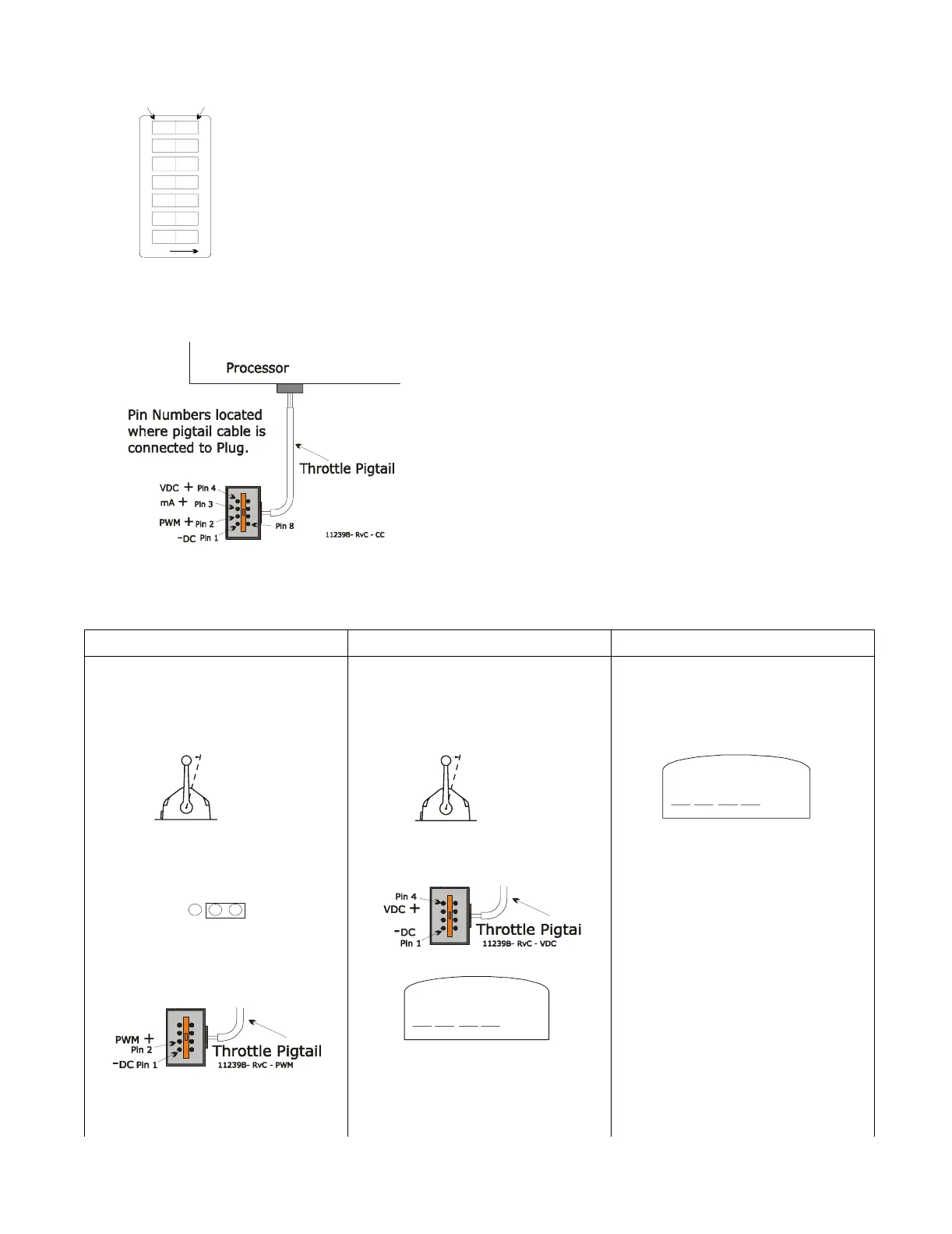
Figure 27: Throttle Connector at Processor
Pigtail
To Measure Throttle Signals:
8 Pin Throttle Connector at the Processor Pigtail
PIN 1 – DC Return
PIN 2 – PWM +
PIN 3 – mA (current) +
PIN 4 – VDC (voltage) +
PIN 8 – Shield Wire
Table 1: Throttle Minimum Output Adjustments
PWM (Duty Cycle) Voltage (VDC) Current (mA)
1) Disconnect the Throttle Wire Harness
from the Throttle Pigtail at the
Processor.
1) Disconnect the Throttle Wire Harness
from the Throttle Pigtail at the
Processor.
1) Disconnect the positive (+) throttle
signal wire from the governor (refer to
the Drawing in Appendix A)
2) Place the Control Head lever into the
Ahead Detent position.
2) Place the Control Head lever into the
Ahead Detent position.
2)Set the Multi meter up as an Amp Meter
(current).
3) Move Jumper 6 on Auxiliary Board to
Pins 2-3 (voltage/current setting).
Refer to Figure 13:, page 25 for
location.
3) Connect the Multi meter to Pins 1 and 4
of the Throttle Connector (Refer to
Figure 27:)
3) Connect one Multi meter probe to the
disconnected positive (+) throttle
signal wire
4) Connect the Multi meter to PWM Pins
on the Throttle Connector (Refer to
Figure 27:).
4) Set Multi meter to the Voltage setting. 4)Connect the other Multimeter probe to
the terminal on the governor.
0657-600
1234567
OFF
To change, use a
small screwdriver.
PUSH DOWN
FOR ‘ON’
PUSH DOWN
FOR ‘OFF’
OFF
OFF
OFF
OFF
OFF
ON
ON
Shield Wire
Move To
Ahead Detent
10161
Move To
Ahead Detent
10161
mA
1 2 3
VDC