Page 4
Standard Cable Connections
Select the desired mounting locations and drill holes per template.
Run cables between Actuator/Processor and Control Head.
At the Control Head, strip back the PVC cover on the shielded cable approximately 2"
(50mm).
Strip and cut off the shielding and drain wire flush with the end of the PVC cover (the
drain wire at the Control Head is not connected to ground).
Strip 3/8" (9,5mm) insulation off each wire.
Twist the individual strands of the wires to minimize fraying.
Crimp a locking fork terminal (included with each Control Head) to each of the conduc-
tors.
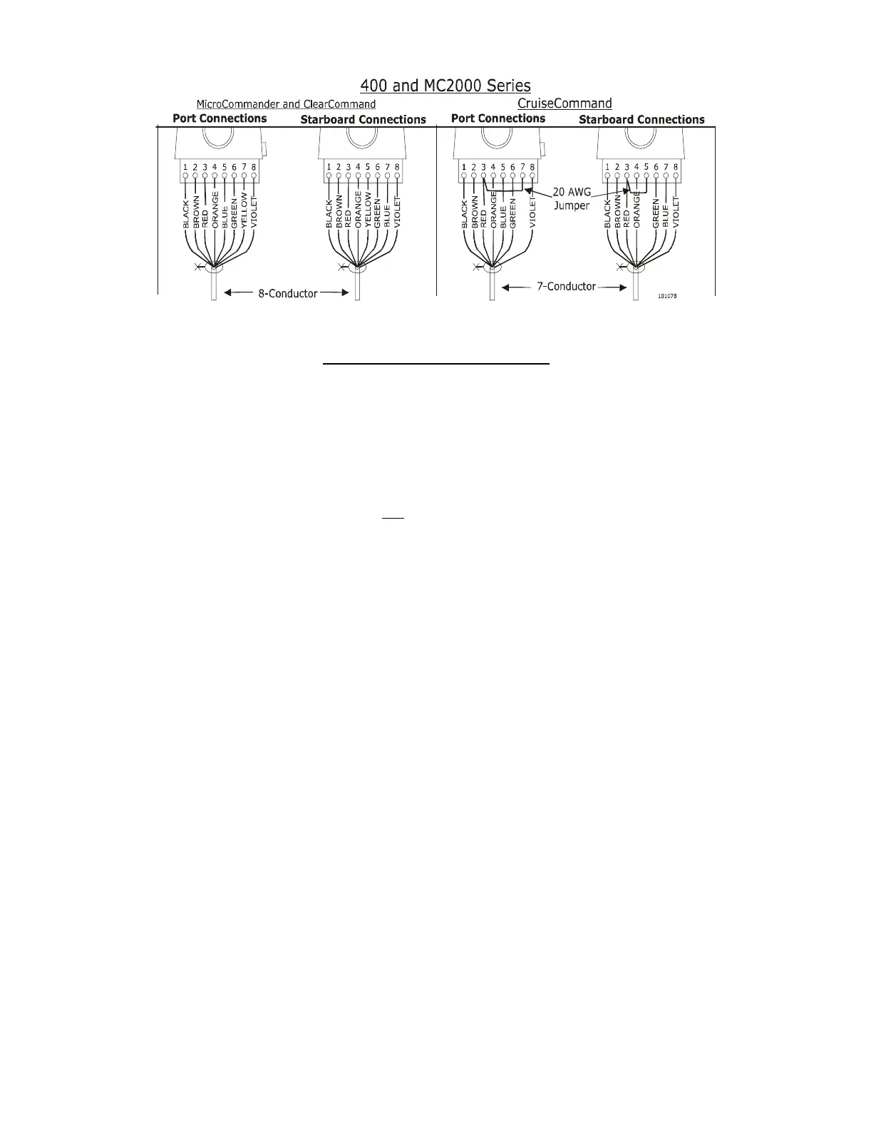
Make connections to the Control Head as shown above for MicroCommander, ClearCom-
mand, and CruiseCommand Systems.
Hand Held Control is a Station option. Contact your ZF Mathers Dealer for further information
on Hand Held requirements and options.