Page 16
E) IMPORTANT NOTE ABOUT BATTERY SOURCES
Whenever the load is turned on, it can be drawing power from the batteries. Therefore, if the batteries are not
simultaneously being recharged, or if charging will not be available for an extended period, it is recommended
that the load be shut off to prevent complete discharge of batteries.
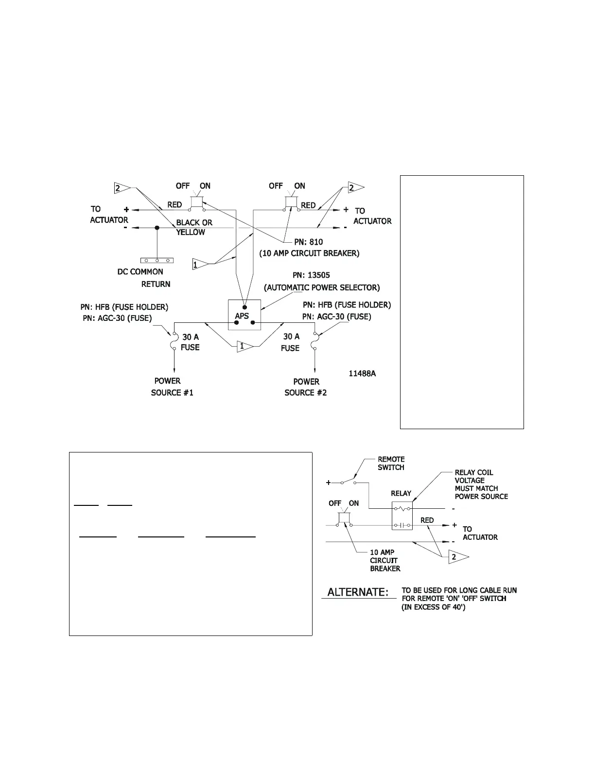
F) INSTALLATION DIAGRAM
Figure 1:
Flag 1: Wire Size (Ref ABYC E9.15.9
10%)
0-15’ 12 AWG (#3 Metric Equiva-
lent)
15’-30’ 10 AWG (#5 Metric Equiva-
lent)
30’-60’ 8 AWG (#8 Metric Equiva-
lent)
Flag 2: Wire Size (Recommended
Twisted Pair)
0-20’ 14 AWG (#2 Metric Equiva-
lent)
20’-40’ 12 AWG (#3 Metric Equiva-
lent)
Note:
1. APS output is strictly for ZF
Mathers Controls
2. Power Sources may be 12 or
24 volts DC
A.P.S. (Auto Power Selector) Kits
Twin Single
Screw
Screw Include the following:
13983 13984
Quantity Description Part Number
1 1 A.P.S. Unit 13505
2 1 10 amp Switch
Circuit Breaker 810
2 2 Fuse Holder In-Line HFB
2 2 30 Amp Fuse AGC-30
Figure 2: