Application macros
58
Default control connections
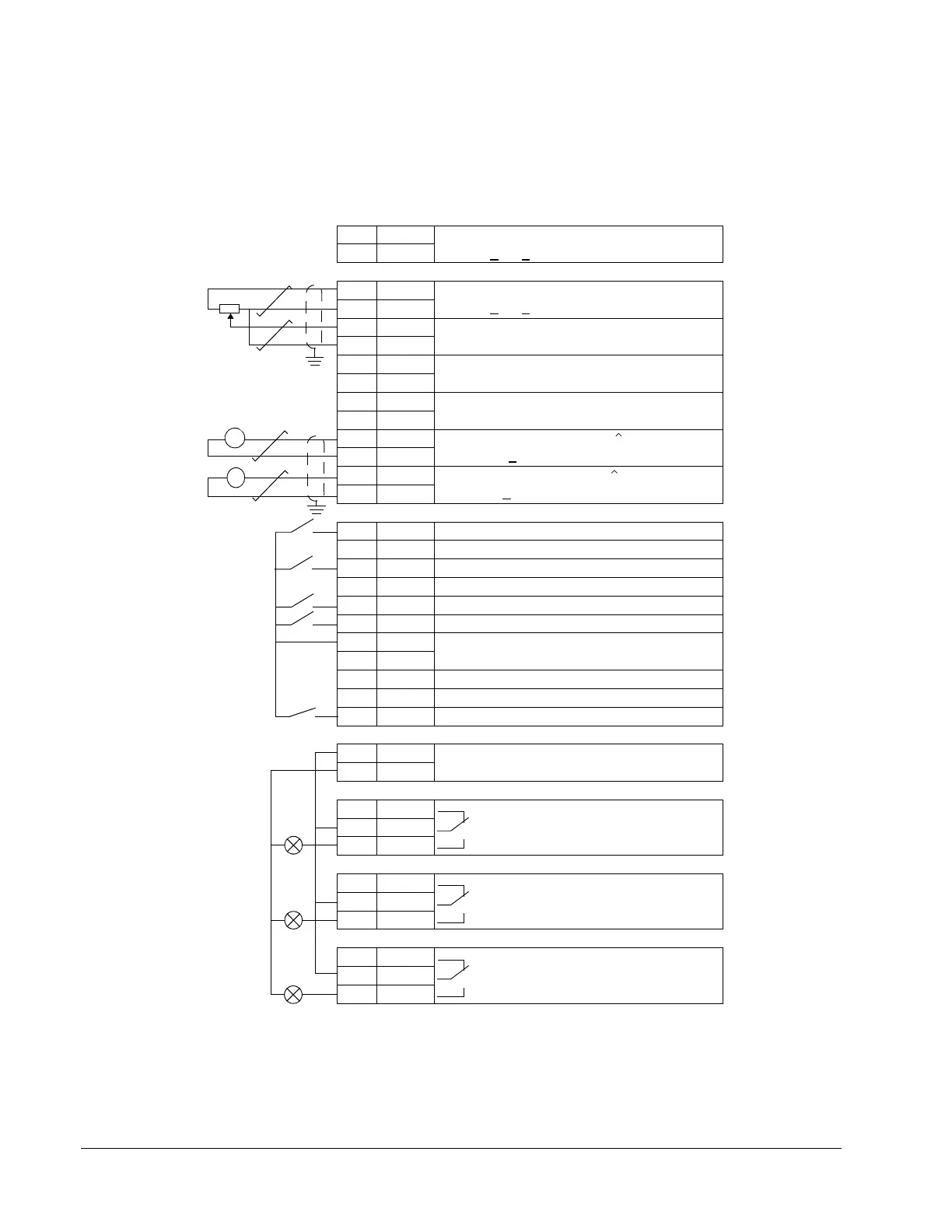
The figure below shows the external control connections for the Tension macro(s).
The markings of the terminals on the RMIO board are visible.
X20
1 VREF Reference voltage -10 VDC
2GND1kOhm <
R
L
< 10 kOhm
X21
1 VREF Speed Reference 0(2)…10 V
1 kOhm <
R
L
< 10 kOhm
2GND
3 AI1+ Speed reference 0(2)…10 V, R
in
> 200 kOhm
4AI1-
5 AI2+ Tension Fdbk Input. 0(4)…20 mA, R
in
=
100 Ohm
6AI2-
7 AI3+ Tension Setpoint. 0(4)…20 mA, R
in
= 100
Ohm
8AI3-
9 AO1+ Output Current 0(4)…20 mA 0…motor nom.
current, R
L
< 700 Ohm
10 AO1-
11 AO2+ Output Speed 0(4)…20 mA 0…motor nom.
speed, R
L
< 700 Ohm
12 AO2-
X22
1 DI1 Stop/Start
2 DI2 By default not in use
3 DI3 Tension Ctrl Enable.
4 DI4 By default not in use
5 DI5 Diameter Reset
6 DI6 Fault Reset
7 +24 V +24 VDC, max. 100 mA
8+24 V
9 DGND1 Digital ground
10 DGND2 Digital ground
11 DIIL Estop Input
X23
1 +24 V Auxiliary voltage output, non-isolated,
24 VDC, 250 mA
2GND
X25
1RO11
Ready
2RO12
3RO13
X26
1RO21
Running
2RO22
3RO23
X27
1 R031
Fault
2 R032
3 R033
=
=
A
rpm
A

 Loading...


