Actual signals and parameters
64
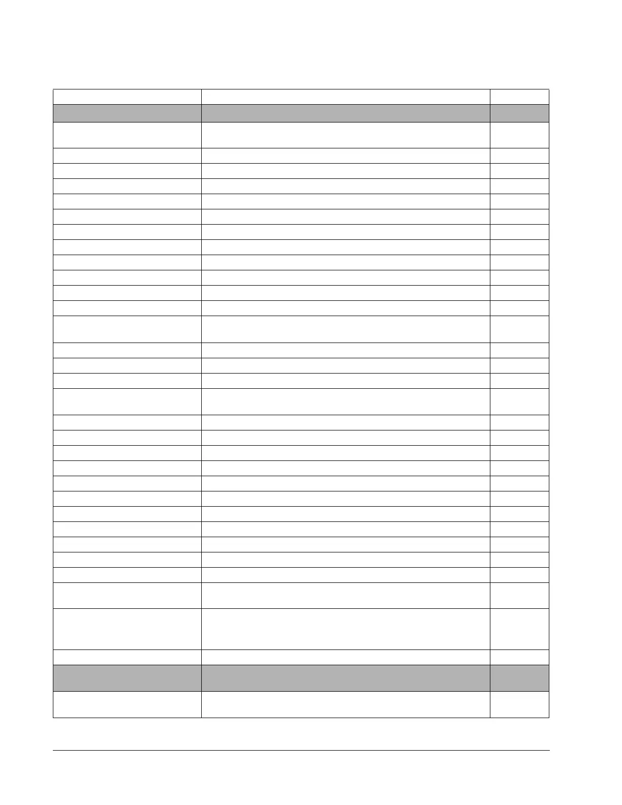
No. Name/Value Description FbEq
01 ACTUAL SIGNALS
Basic signals for monitoring of the drive.
01.02 MOTOR SPEED FILT Calculated motor speed in rpm. 100% corresponds to 11.05 EXT
REF1 MAXIMUM.
200 = 1%
01.03 FREQUENCY Calculated output frequency. 100 = 1 Hz
01.04 CURRENT Measured motor current. 10 = 1 A
01.05 TORQUE Calculated motor torque. 100% is the motor nominal torque. 100 = 1%
01.06 POWER Motor power. 100% is the nominal power. 10 = 1%
01.07 DC BUS VOLTAGE Measured intermediate circuit voltage. 1 = 1 VDC
01.08 MAINS VOLTAGE Calculated supply voltage. 1 = 1 VAC
01.09 OUTPUT VOLTAGE Calculated motor voltage. 1 = 1 VAC
01.10 ACS800 TEMP Calculated IGBT temperature. 100% is the trip point 10 = 1%
01.14 OP HOUR COUNTER Elapsed time counter. Runs when the control board is powered. 1 = 1 h
01.15 KILOWATT HOURS kWH counter. 1 = 100 kWH
01.16 APPL CODE DUTY Control program code load. 1 = 1%
01.17 DI6-1 STATUS Status of digital inputs. Example: 000001 = DI1 is on, DI2 to DI6 are
off.
1 = 1
01.18 AI1 [V] Value of analog input AI1. 1000 = 1 V
01.19 AI2 [mA] Value of analog input AI2 1000 = 1 mA
01.20 AI3 [mA] Value of analog input AI3 1000 = 1 mA
01.21 RO3-1 STATUS Status of relay outputs. Example: 001 = RO1 is energized, RO2 and
RO3 are de-energized.
1 = 1
01.22 AO1 [mA] Value of analog output AO1. 1000 = 1 mA
01.23 AO2 [mA] Value of analog output AO2. 1000 = 1 mA
01.28 AO3 [mA] Value of output 1 of the Analog I/O Extension module (optional). 1000 = 1 mA
01.29 AO4 [mA] Value of output 2 of the Analog I/O Extension module (optional). 1000 = 1 mA
01.35 MOTOR 1 TEMP Measured temperature of motor 1. See 35.01 MTR1 TEMP SEL. 1 = 1
o
C
01.36 MOTOR 2 TEMP Measured temperature of motor 2. See 35.04 MTR2 TEMP SEL. 1 = 1
o
C
01.37 MOTOR TEMP EST Estimated motor temperature. 1 = 1
o
C
01.38 AI5 [mA] Value of input 1 of the Analog I/O Extension module (optional). 1000 = 1 mA
01.39 AI6 [mA] Value of input 2 of the Analog I/O Extension module (optional). 1000 = 1 mA
01.40 DI7-12 STATUS Status of digital inputs of the Digital I/O Extension modules (optional). 1 = 1
01.41 RO4-7 STATUS Status of digital outputs of the Digital I/O Extension modules (optional). 1 = 1
01.43 MOTOR RUN-TIME Motor run time counter. The counter runs when the inverter
modulates.
1 = 10 h
01.44 FAN ON-TIME Running time of the drive cooling fan.
Note: The counter can be reset by the DriveWindow PC tool.
Resetting is recommended when the fan is replaced.
1 = 10 h
01.45 CTRL BOARD TEMP Control board temperature. 1 = 1
o
C
02 ACTUAL SIGNALS
Speed and torque reference monitoring signals and control program
values.
02.01 SPEED REF 2 Limited speed reference. 100% corresponds to 11.05 EXT REF1
MAXIMUM.
200 = 1%

 Loading...


