3.3.9 Inspecting additional mechanical stops
Location of additional mechanical stops
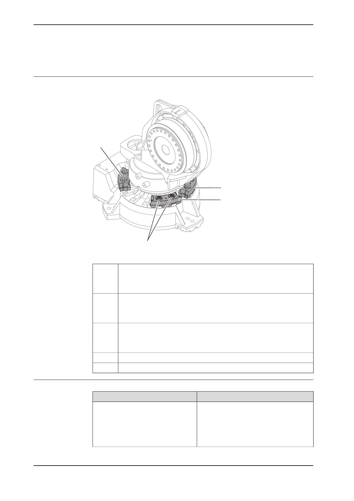
The figure shows the location of the additional stops.
xx0800000273
Movable mechanical stop. Limited to:
• -126° (IRB 2600 Type C-20/1.65, IRB 2600 Type C-12/1.65)
• -129° (IRB 2600-20/1.65, IRB 2600-12/1.65, IRB 2600-12/1.85, IRB 2600ID-
15/1.85, IRB 2600ID-8/2.0)
A
Movable mechanical stop. Limited to:
• +13.5° (IRB 2600 Type C-20/1.65, IRB 2600 Type C-12/1.65)
• +16.5° (IRB 2600-20/1.65, IRB 2600-12/1.65, IRB 2600-12/1.85, IRB 2600ID-
15/1.85, IRB 2600ID-8/2.0)
B
Movable mechanical stop. Limited to:
• -13.5° (IRB 2600 Type C-20/1.65, IRB 2600 Type C-12/1.65)
• -16.5° (IRB 2600-20/1.65, IRB 2600-12/1.65, IRB 2600-12/1.85, IRB 2600ID-
15/1.85, IRB 2600ID-8/2.0)
C
Attachment screwsD
WashersE
Required equipment
NoteEquipment etc.
Includes:
• Stop
• Attachment screws plus washers
• Document for movable mechanical stop
For spare part number see Spare part lists on
page 445.
Mechanical stop set, axis 1
Continues on next page
140 Product manual - IRB 2600
3HAC035504-001 Revision: Q
© Copyright 2009-2018 ABB. All rights reserved.
3 Maintenance
3.3.9 Inspecting additional mechanical stops

 Loading...


