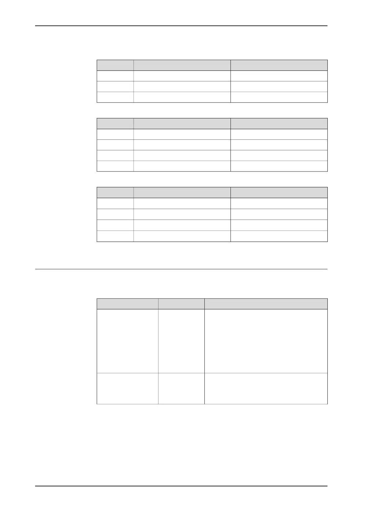
Max. load (emergency stop)Endurance load (in operation)Force
2750 ±3970 N2750 ±1420 NForce z
±7690 Nm±3360 NmTorque xy
±3050 Nm±1120 NmTorque z
Wall mounted
Max. load (emergency stop)Endurance load (in operation)Force
2750 ±4600 N2750 ±880 NForce xy
±4560 N±1780 NForce z
1470 ±5620 Nm1470 ±1990 NmTorque xy
±3130 Nm±1150 NmTorque z
Suspended
Max. load (emergency stop)Endurance load (in operation)Force
±5380 N
i
±2250 N
i
Force xy
-2750 ±4280 N
i
-2750 ±1420 N
i
Force z
±7800 Nm
i
±3440 Nm
i
Torque xy
±3050 Nm
i
±1110 Nm
i
Torque z
i
Only valid for IRB 2600-20/1.65, IRB 2600-12/1.65, IRB 2600-12/1.85, IRB 2600ID-15/1.85, IRB
2600ID-8/2.0.
IRB 2600 Type C-20/1.65, IRB 2600 Type C-12/1.65 is not available for suspended installation.
Requirements, foundation
The table shows the requirements for the foundation where the weight of the
installed robot is included:
NoteValueRequirement
Flat foundations give better repeatability of the
resolver calibration compared to original settings
on delivery from ABB.
0.5 mmFlatness of foundation
surface
The value for levelness aims at the circumstance
of the anchoring points in the robot base.
In order to compensate for an uneven surface,
the robot can be recalibrated during installation.
If resolver/encoder calibration is changed this
will influence the absolute accuracy.
The limit for the maximum payload on the robot
is reduced if the robot is tilted from 0°.
15°Maximum tilt
Contact ABB for further information about accept-
able loads.
Continues on next page
52 Product manual - IRB 2600
3HAC035504-001 Revision: Q
© Copyright 2009-2018 ABB. All rights reserved.
2 Installation and commissioning
2.2.1 Pre-installation procedure
Continued

 Loading...


