4.8.3 Replacing gearbox axis 3
Location of gearbox axis 3
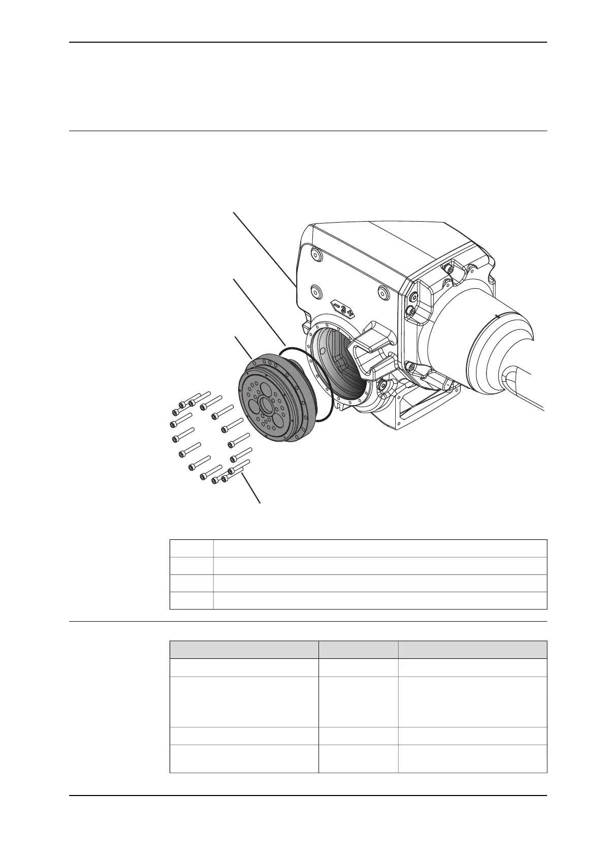
The gearbox is located as shown in the figure.
The figure shows the standard version of IRB 2600. Assembly is the same for IRB
2600ID.
xx0900000381
Upper armA
O-ringB
Gearbox, axis 3C
Attachment screws M6x40 quality Steel 12.9 Gleitmo (16 pcs)D
Required equipment
NoteArt. no.Equipment
See Spare part lists on page 445.Gearbox
2 pcs, dimension: M6. 2 pcs, dimen-
sion: M8.
Guide pins
Used to guide the gearbox and the
upper arm during removal/refitting.
3HAB7887-1Rotation tool
Content is defined in section
Standard tools on page 441.
Standard toolkit
Continues on next page
Product manual - IRB 2600 383
3HAC035504-001 Revision: Q
© Copyright 2009-2018 ABB. All rights reserved.
4 Repair
4.8.3 Replacing gearbox axis 3

 Loading...


