InformationAction
Art. no. is specified in Required equip-
ment on page 275.
xx1100000688
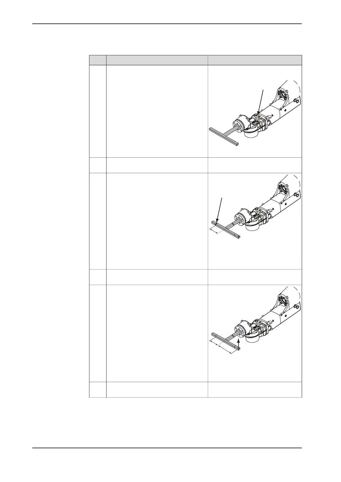
Fit the measuring bracket to the wrist. Use
the holes that are pointed out in the figure.
5
Fit the magnetic foot of the dial indicator
on the measuring bracket.
6
xx1100000690
Place the tip of the dial indicator on the
marking.
7
Distance from the rotation center of axis
6:
A 100 mm
Verify that axis 6 is put in calibration posi-
tion.
8
xx1100000692
A 100 mm (dial indicator)
B 140 mm
Apply load F=40N upwards with a dynamo-
meter on the opposite side of the dial indic-
ator, at a distance B from the rotation cen-
ter of axis 6.
9
Remove the load and set the dial indicator
to zero.
10
Continues on next page
276 Product manual - IRB 2600
3HAC035504-001 Revision: Q
© Copyright 2009-2018 ABB. All rights reserved.
4 Repair
4.4.7 Measuring the play, axis 6 (ID upper arm)
Continued

 Loading...


