Mechanical installation
Geometric adjustment of track motion
2-18 3HEA 800 970-001 Rev. D, Mars 2006
Installation and operation
IRBT 4003S In-
line
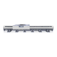
layout åkvagn_4400_in-line.wmf
Figure 10 Carriage layout 4003S, in-line
Item Description Item Description
1 Vernier scale 3 X positive direction
2 Robot center when track motion is at
position X-zero
4 Mounting hole
Action Info/Illustration
2. The values taken from the virtual layout must be
transferred and implemented on the track motion by
placing the prism along the motion in steps of 1 m to
obtain X-, Y- and Z-values that correspond to the
virtual values.
3. The prism is placed at the edge of the vertically
mounted linear guide and above the horizontally
mounted linear guide; see Figure 11.
Begin by adjusting the level
of the vertical linear guide.
4. When the vertical linear guide is measured, the prism
should have an angle bracket so that both the Y- and
Z-values can be adjusted.
5. When the vertical linear guide matches the virtual
layout, the horizontal linear guide can be adjusted
either through further measurement or by using a spirit
level on the robot's mounting surface on the carriage.
 Loading...