Operation principle and hardware description 37
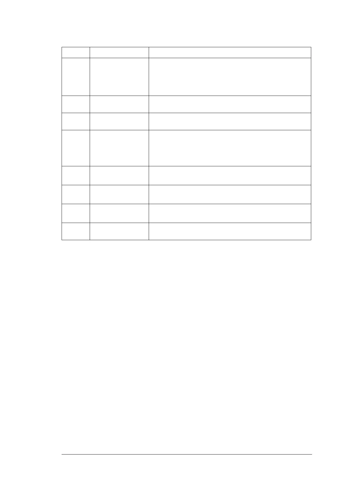
Q1 AC main switch-
disconnector
Hand-operated switch which connects the inverter to the electrical
power system.
The AC main switch-disconnector can be operated at all times. If it is
operated during operation, the inverter will trip as the grid
disappears.
Q2 DC main switch Hand-operated switch which connects the inverter to the solar
generator.
Q10 Auxiliary control
voltage switch
Hand-operated switch which connects the auxiliary control voltage to
the inverter.
T10 Auxiliary voltage
transformer (with
options +G396,
+G397, +G398 and
+G415)
Provides auxiliary voltage for the inverter circuit boards, cooling fans
and contactor control circuits.
U1
U3
Inverter module Converts the DC voltage to AC voltage. The operation is controlled
by switching the IGBTs.
U2
U4
LCL filter Smooths the current and voltage waveform.
Z1.1-3
Z2.1-3
Common mode filter The filter reduces common mode voltages and currents in the solar
generator and inverter main circuit and AC output.
Z10 EMC filter (option
+E216)
EMC filter for low voltage distribution networks.
Symbol Terminal/Component Description/Operation

 Loading...


