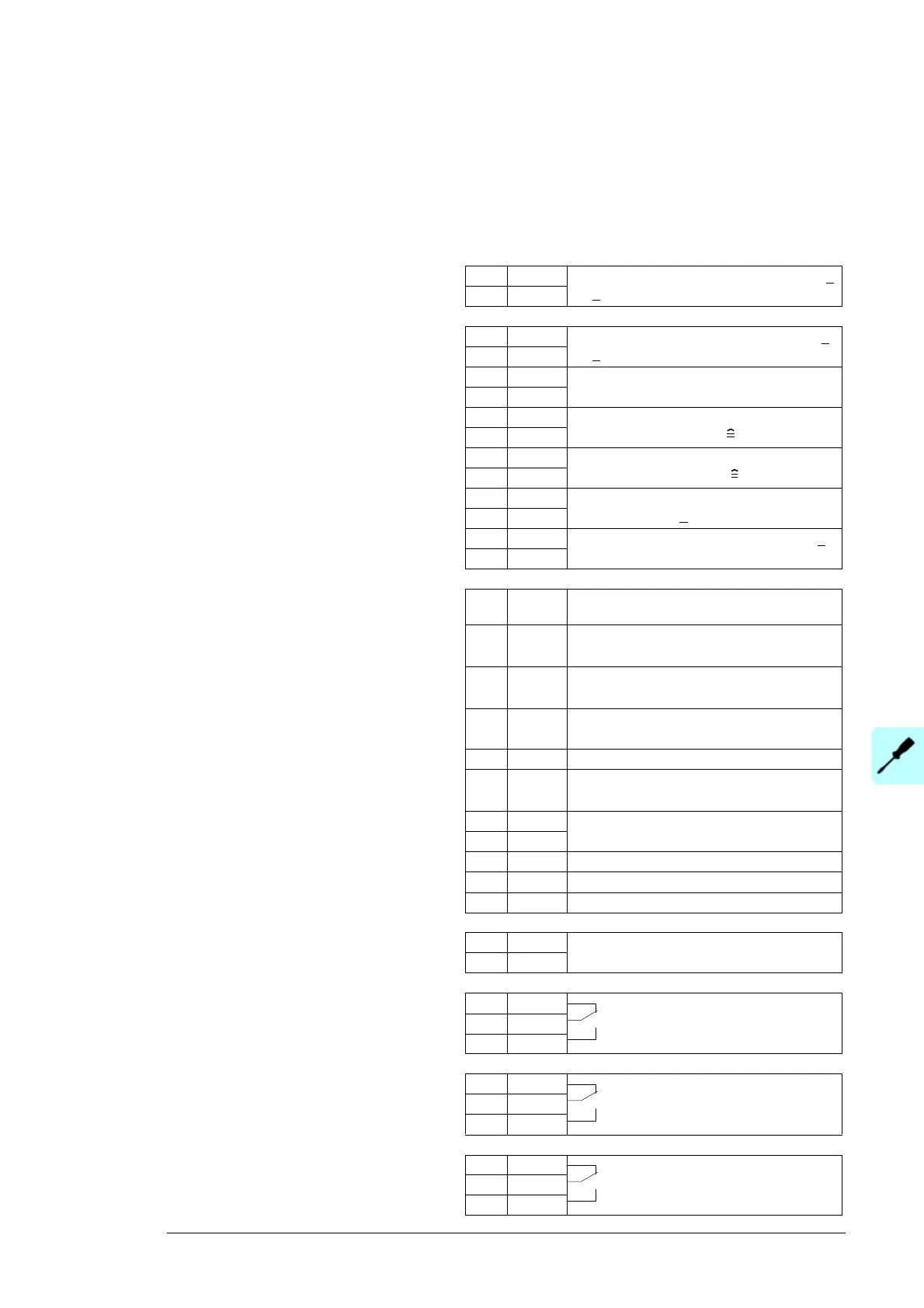
RMIO
X20
1 VREF- By default, not in use. -10 V DC, 1 kohm <
R
L
< 10 kohm
2AGND
X21
1 VREF+ By default, not in use. 10 V DC, 1 kohm <
R
L
< 10 kohm
2AGND
3 AI1+ Insulation resistance measurement
0 … 10 V (option +Q954), R
in
= 200 kohm
4AI1-
5 AI2+ AC cubicle ambient temperature
measurement 4...20 mA -30…+80 °C.
6AI2-
7 AI3+ DC cubicle ambient temperature
measurement. 4...20 mA -30…+80 °C.
8AI3-
9 AO1+ Fan speed control for LCL filters.
0(4)…20 mA, R
L
< 700 ohm
10 AO1-
11 AO2+ By default, not in use. 0(4)…20 mA, R
L
<
700 ohm
12 AO2-
X22
1 DI1 Fan acknowledgement and LCL filter
temperature supervision
2 DI2 Run enable. 0 = Inverter run is disabled
1 = Inverter run is enabled
3 DI3 Status of the AC contactor K1.1.
0 = Open, 1 = Closed
4 DI4 Ground fault supervision (options +Q954,
+Q976 and +Q981)
5 DI5 By default, not in use.
6 DI6 Status of the 24 V auxiliary power buffer.
0 = Buffer is not full, 1 = Buffer is full
7 +24VD +24 V DC max. 100 mA
8 +24VD
9 DGND1 Digital ground
10 DGND2 Digital ground
11 DIIL By default, not in use.
X23
1 +24V Auxiliary voltage output and input, non-
isolated, 24 V DC 250 mA
1)
2GND
X25
1 RO1 Relay output 1: Charging contactor
control
2RO1
3RO1
X26
1 RO2 Relay output 2: Control of the AC
contactor K1.3
2RO2
3RO2
X27
1 RO3 Relay output 3: Control of the AC
contactor K1 / K1.1.
2RO3
3RO3
Terminal block size:
cables 0.3 to 3.3 mm
2
(22 to 12 AWG)
Tightening torque:
0.2 to 0.4 N·m
(0.2 to 0.3 lbf·ft)
1) Total maximum current shared
between this output and the
optional modules installed on the
board.

 Loading...


