94 Electrical installation
Default I/O connections (RDIO on RDCU – A41)
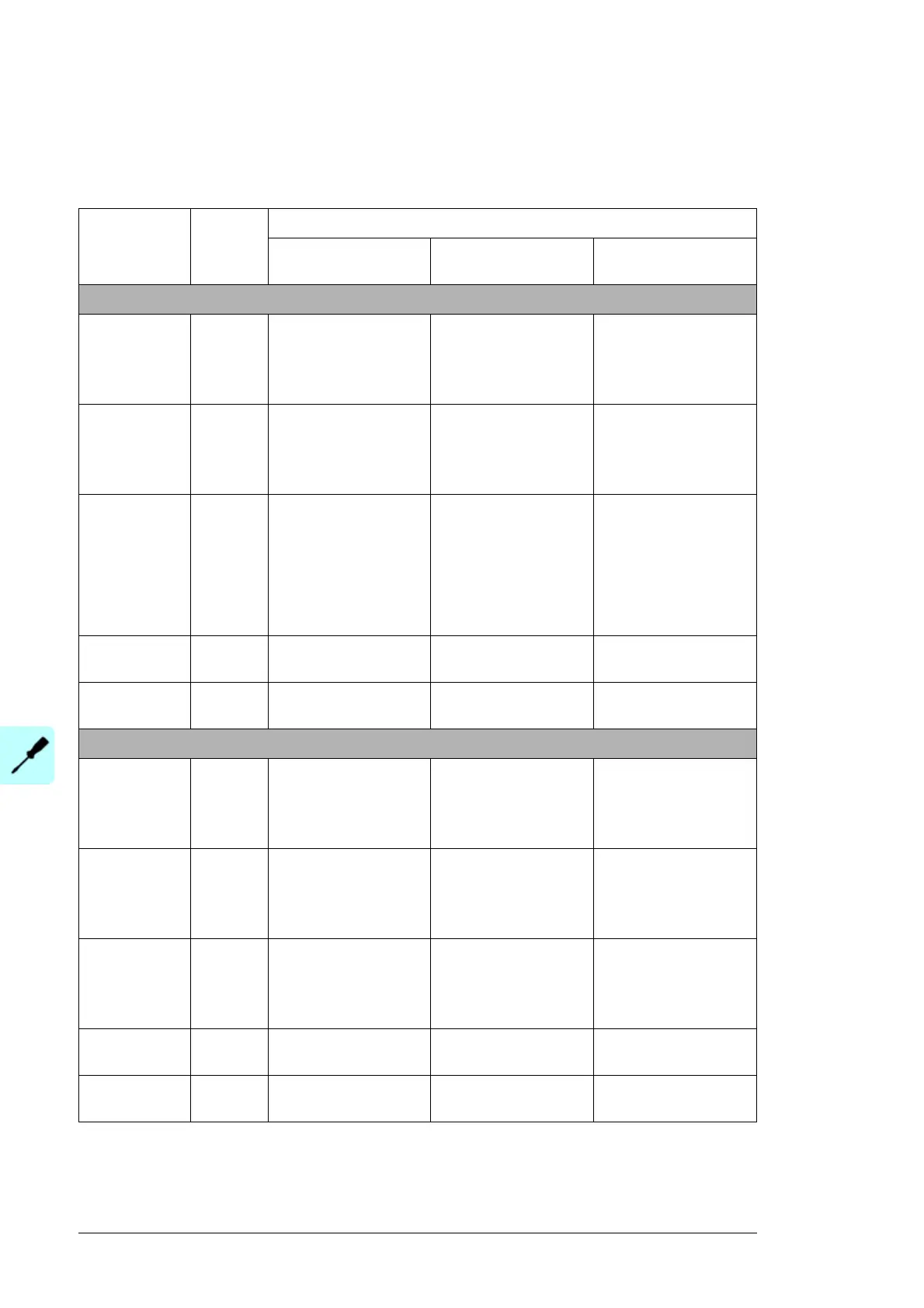
The default connections of the RDIO-01 digital I/O extension modules inserted on the
inverter control unit are shown below.
Digital
input/output
RDIO
terminal
Description
100 kW and 250 kW
units
500 kW and 630 kW
units
875 kW and 1000 kW
units
RDIO-01 no. 1 on Slot 2 – A412
Digital input 1 X11:DI1 Status of the DC
contactor K2.
0 = Open
1 = Closed
Status of the DC
contactor K2.1.
0 = Open
1 = Closed
Status of the DC
contactor K2.1.
0 = Open
1 = Closed
Digital input 2 X12:DI2 - Status of the DC
contactor K2.2.
0 = Open
1 = Closed
Status of the DC
contactor K2.2.
0 = Open
1 = Closed
Digital input 3 X12:DI3 Status of the grid
monitoring relay
(options +Q969,
+Q974, +Q975 and
+Q980)
0 = Grid is not OK
1 = Grid is OK
Status of the grid
monitoring relay
(options +Q969,
+Q974, +Q975 and
+Q980)
0 = Grid is not OK
1 = Grid is OK
Status of the grid
monitoring relay
(options +Q969,
+Q974, +Q975 and
+Q980)
0 = Grid is not OK
1 = Grid is OK
Relay output 1 X21:RO1 Control of the DC
contactor K2.
Control of the DC
contactor K2.1.
Control of the DC
contactor K2.1
Relay output 2 X22:RO2 - Control of the DC
contactor K2.2.
Control of the DC
contactor K2.2
RDIO-01 no. 2 on Slot 1 – A411
Digital input 1 X11:DI1 - Status of the AC
contactor K1.2.
0 = Open
1 = Closed
Status of the AC
contactor K1.2.
0 = Open
1 = Closed
Digital input 2 X12:DI2 - - Status of the AC
contactor K1.3.
0 = Open
1 = Closed
Digital input 3 X12:DI3 - - Status of the DC
contactor K2.3.
0 = Open
1 = Closed
Relay output 1 X21:RO1 - Control of the AC
contactor K1.2
Control of the AC
contactor K1.2
Relay output 2 X22:RO2 - - Control of the DC
contactor K2.3

 Loading...


