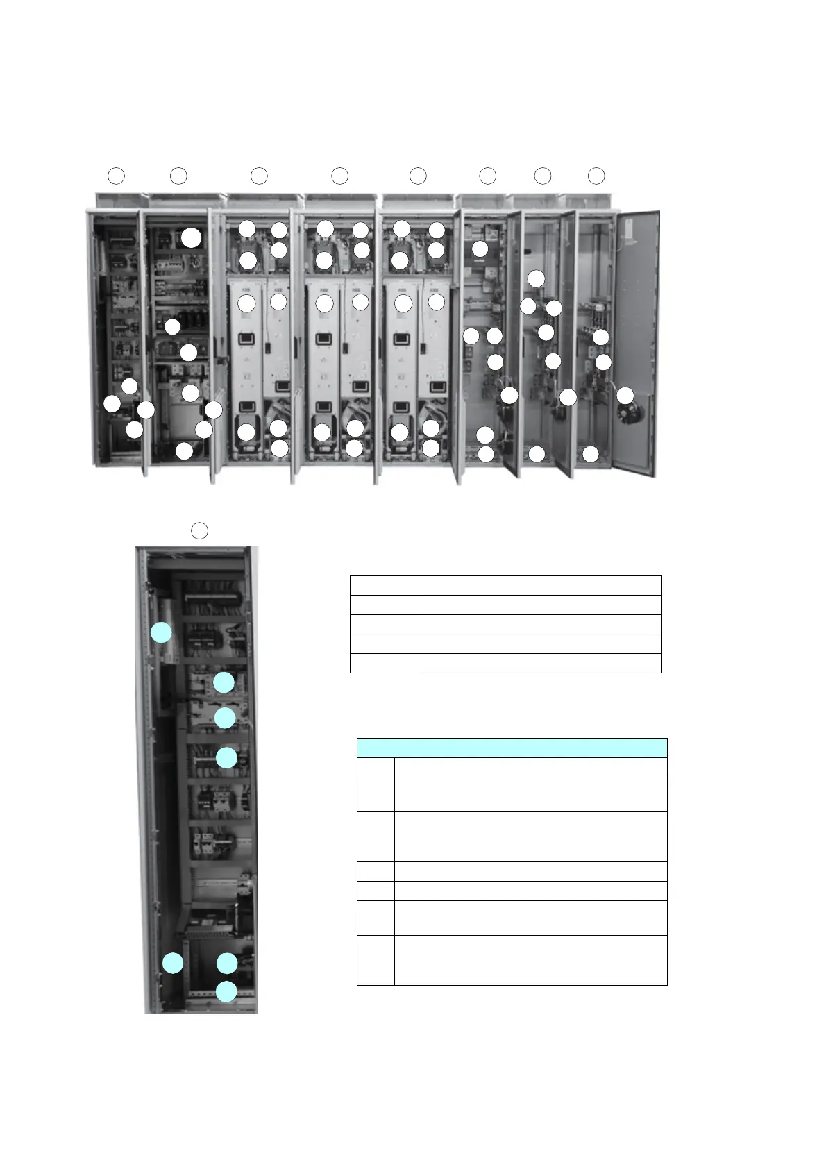
External control interfaces
23 Junction box power supply (option +G410)
24 115/230 V auxiliary control voltage connection
terminals and switch (Q10)
25 RDCU control unit (A41, inverter control unit).
Optional fieldbus adapter modules: +K454,
+K458, +K466, +K479.
26 RDCU control unit (A43, master control unit)
27 APBU branching unit
28 NETA-01 Intelligent Ethernet adapter module
(option +K464)
29 NETA-21 remote monitoring tool (option +K484)
and VSN700-05 data logger (options +K485 and
+K486)
A
Cubicles
A Auxiliary control cubicle
B Output cubicle
C Inverter module cubicle
D Incoming cubicles
27
25
26
24
23
28
29

 Loading...


