90 Electrical installation
Connecting the DC current measurement signals to an
external controller (option +G416)
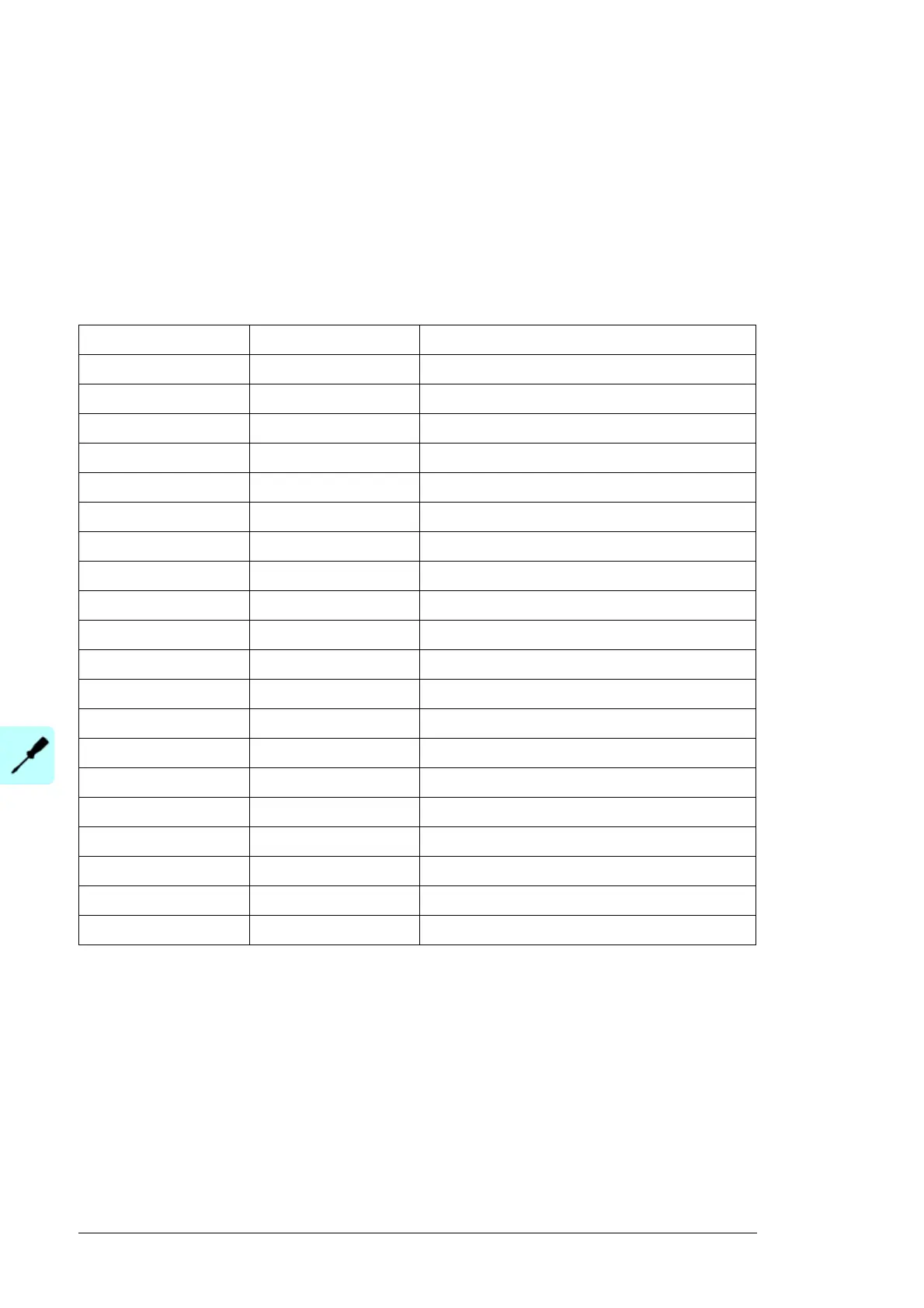
This table shows the terminals for connecting the DC current measurement signals
(0…4 V) to an external controller. The terminals for connecting the grounding wires are
X50:9 and X50:29. For DC input options +4H382 and +5H382, the terminal block is
located in the first incoming cubicle (DCU1). For the other DC input options, the terminal
block is located in the second incoming cubicle (DCU2). Lead the control cables to the
applicable incoming cubicle through the bottom lead-through.
Number of DC input DC input fuse Current measurement output terminal
1 F3:1 X50:11
2F3:2 X50:12
3F3:3 X50:13
4F3:4 X50:14
5F3:5 X50:15
6F3:6 X50:16
7F3:7 X50:17
8F3:8 X50:18
9F3:9 X50:19
10 F3:10 X50:20
11 F3:11 X50:31
12 F3:12 X50:32
13 F3:13 X50:33
14 F3:14 X50:34
15 F3:15 X50:35
16 F3:16 X50:36
17 F3:17 X50:37
18 F3:18 X50:38
19 F3:19 X50:39
20 F3:20 X50:40

 Loading...


