86 Electrical installation
DC input cable connection procedure
1. Remove the shroud covering the input power terminals.
2. Lead the cable(s) into the inside of the cabinet. If a shielded cable is used, connect the
shield to the cabinet grounding busbar with a cable lug.
3. Connect the DC- conductor to terminal L- and the DC+ conductor to terminal L+.
Note: In the R8i, 2 × R8i and 3 × R8i frame sizes with fuse-protected DC input
connections, the location of the + and - terminals varies depending on the number of
the DC input connections. See chapter Dimension drawings.
4. If a separate PE conductor is used, connect it to the cabinet grounding terminal.
5. Refit the shroud onto the input power terminals.
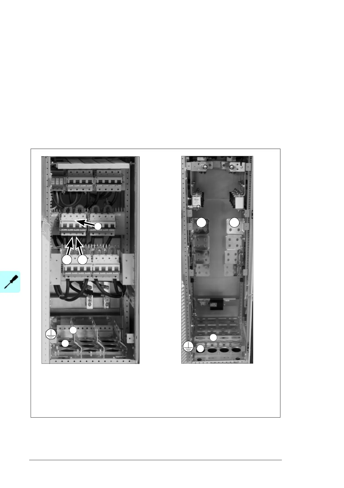
DC input terminals of frame R7i with option +H377
(four miniature circuit breakers for four DC input
connections)
a) Cable lead-throughs
b) Cable support
b) DC input miniature circuit breakers
a
b
L+ L-
c
DC input terminals of frame R8i with option
+4H382 and frame 2 × R8i (four fuse-
protected DC input connections)
a) Cable lead-throughs
b) Cable support
a
b
L+ L-

 Loading...


