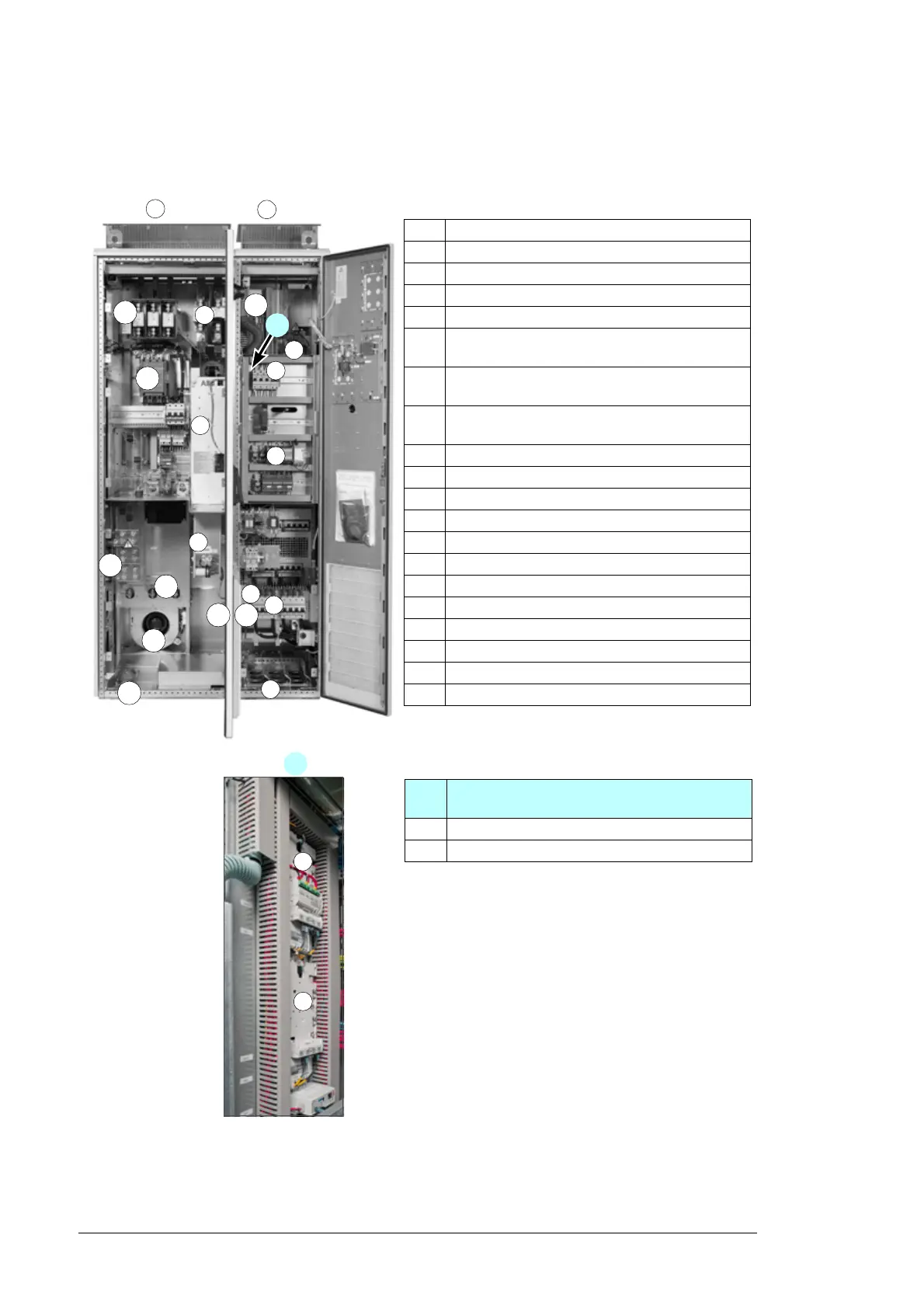
Description
A Incoming cubicle
B Inverter module cubicle
1 DC cable lead-throughs
2 Photovoltaic generator connection terminals
3 Auxiliary control voltage connection terminals
and switch
4 Ground fault monitoring device (options +Q954
and +Q976)
5 Grid monitoring relay (options +Q969 and
+Q974)
6 DC contactor
7 Inverter DC fuses
8 Inverter module
9 Inverter module cooling fan
10 LCL filter
11 LCL filter cooling fan
12 AC contactor
13 AC main switch-disconnector with fuses (Q1)
14 AC output (grid connection) terminals
15 AC output cable lead-throughs
16 Heating resistor (option +G300)
17 Junction box power supply (option +G410)
11
1
2
13
14
15
12
B
3
8
5
6
7
2
1
18
9
A
18 External control interfaces (behind the
swing-out frame)
1 RDCU control unit (A41, inverter control unit)
2 RDCU control unit (A43, master control unit)
4
10
16 16
17
18

 Loading...


